


The Frame
In our last installment, we covered how I would be capturing and recording GPS positioning data during MARV's flights, and today we will finally get to build the quadcopter frame. I apologize for skipping a month updating this project, but life caught up with me quite quickly. I was finally able to finalize the frame design, and I wound up designing and re-printing new motor mounts. This was necessary because the original mounts, which were part of the download from Thingiverse, did not fit the motors I asked HobbyKing to send me.
The new motor mounts can be found on my personal Thingiverse account and will work with most of the Turnigy Park series of brushless out runners. The old style would have most likely worked fine with HobbyKing's Multistar brand of brushless motors as they are designed specifically for multirotor aircraft. I have also included the Sketchup file with the motor mounts, so you can easily modify the mounts to fit your design.
Moving forward, it's time to assemble our quadcopter's frame. The Anycopter design utilizes one-half-inch square wooden dowels due to their light weight and cost. If you buy them from Home Depot or Lowes and cut them down to size yourself, they will work out to costing about $0.75 each for 12-inch arms. This means that you can break as many as you would like, and for less than a buck, you have a new arm. Their other advantage is that they will snap long before the rest of your frame will, and in doing so, they will absorb most of the shock forces in a crash. This results in less damage to the expensive parts of your frame.
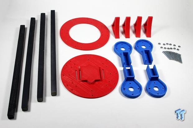
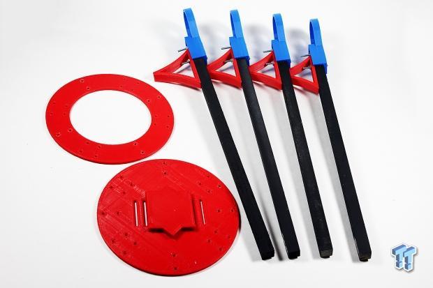
With everything laid out, you see just how simple the Anycopter frame actually is. The entire thing consists of four arms, four landing legs, four motor mounts, and an upper and lower main body. The whole thing is fastened together using a grand total of sixteen 4-32 machine screws and sixteen 4-32 nuts. As you can see here, I spray painted the spars black as I originally wanted an all red and black quadcopter, but the lack of red 3D printing filament when it came time to print the new mounts ruined that thought. I should also note that I chose to use zinc plated machine screws instead of stainless as the zinc plated screws were about one-tenth of the cost of stainless. I bought a box of 100 for about $4.50, whereas the stainless were $1.15 for 2.
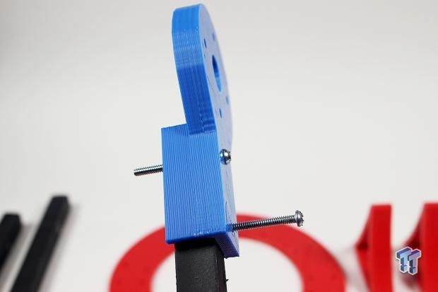
I designed the holes in the motor mounts so that they would need to be chased with a drill bit to ensure perfect roundness and a snug fit. In fact, they were so snug after drilling, that I had to screw them all the way through both the plastic mount and the wooden arm. Next time around, I will make the mounting holes a little larger and use a larger drill bit to ream them out so as to make field repairs easier and faster.
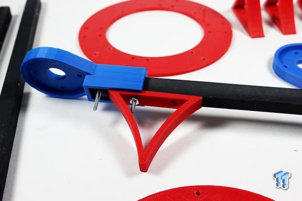
You will notice that I chose to only use one mounting point on the landing legs and to share that with one of the motor mount screws. This decision was made to cut down on cost and to save weight. The legs actually fit inside of the excess motor mount walls, which makes for a very secure and snug fit. If I have to land the copter hard enough to move these legs, I have more things to worry about than them breaking.
With all four of the arms assembled, it is time to move on to attaching them to the quadcopter's main frame. The Anycopter design is capable of supporting up to eight arms at once, so pay attention to the orientation, and select the correct one for a quadcopter. If you make a mistake here, then you will have to disassemble this step and start over.
Our Latest Editorials Article Coverage
- Connected Cars: The technology is here, so let's enjoy it
- Future of wearables unknown, but things are looking good
- Virtual reality provides great long-term potential, be excited
- Artificial intelligence worries smart people, should we be worried?
- Amateur Radio is Still Alive and Kicking: Journey to Becoming a HAM
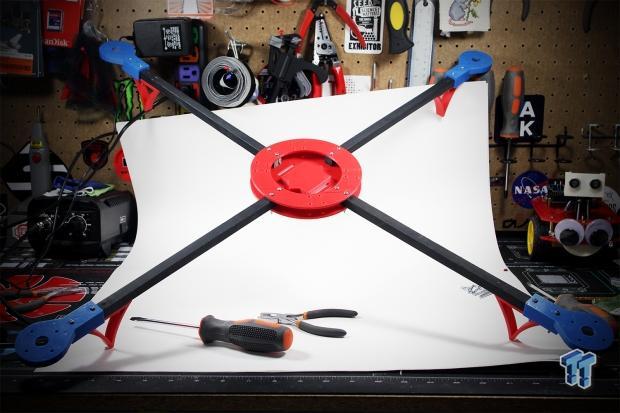
Once everything is assembled, make sure to align the arms so that they are as close to 90 degrees from each other as possible, and to snug the nuts down tight. No thread locker, glue, or anything else is needed to keep the nuts tight, but if you are unsure, add a dab of hot glue to each where the nut meets the bolt. This will prevent anything from coming lose during flight.
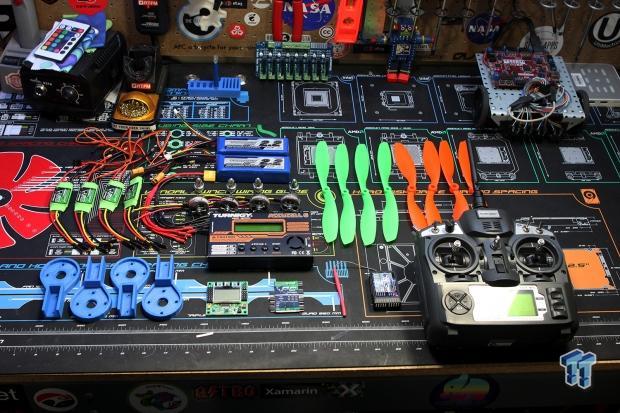
That pretty much wraps up the frame build. I apologize for this being such a short installment, but I promise that there will be some massive excitement in the next segment as the full parts shipment from HobbyKing has arrived. HobbyKing was kind enough to donate all of the electronic parts, propellers, and even a brand new Turnigy 9X 9-channel radio and receiver for this project, and I cannot thank them enough for their generosity. A full list of the parts they have donated is listed below.
1x Turnigy 9x Radio and Receiver
1x Turnigy Accucel Balance Charger
2x Turnigy 3S 2100mAh LiPo Batteries
4x Turnity Park 300 Brushless Outrunner Motors
4x Multistar 15amp ESCs
12x Slow Fly Propellers
1x KK2.2 Flight Controller Board
1x Wiring Harness
1x MultiStar ESC Programming Card
Again, I cannot thank HobbyKing enough for their generosity, and without their support, this project would have never gotten off the ground--pun definitely intended. With the addition of the 9-channel radio and receiver, I have changed my plans to now include a full brushless pan and tilt gimbal on the quadcopter, and I will be printing out some new taller landing legs once I am comfortable enough flying MARV to attach $500 worth of camera gear.
Stay tuned to TweakTown.com for the next installment of Project MARV where we will be installing all of the hardware to the chassis and spinning things up for the first time. I may even create a spin-off post that covers balancing propellers using a cheap laser pointer and scotch tape.
 M3D Micro 3D Printer Review
 Intel Curie-based Arduino 101 Programmable Microcontroller Review
 Connected Cars: The technology is here, so let's enjoy it
 Future of wearables unknown, but things are looking good
 Virtual reality provides great long-term potential, be excited
 New Witcher 3 DLC 'Songs of the Past' confirmed, a prelude to The Witcher 4
 NVIDIA showcases updated DLSS 5 with developer tools that help 'preserve artistic intent'
 RAM shortages could continue for another decade, warns ADATA chairman
 NVIDIA's Synthetic Video Detector can detect AI-generated video with 92% accuracy in less than a second
 Sony patent reveals how the PS6 could dramatically outperform the PS5
 You can now check GDDR7 memory temps on GeForce RTX 50 Series GPUs per module thanks to the work of modders
 Samsung's new OLED panels for laptops push peak brightness to 1,600 nits, enough for a bright outdoors setting
 MSI introduces minimalist and compact GeForce RTX 5080 INSPIRE in all-black
 Razer's new Hammerhead V3 X gaming earbuds come in Xbox and PlayStation flavors
 PS Plus pre-order charts show gamers lean towards higher-priced editions, suggests new price tolerance threshold
 SteelSeries Arctis Nova Pro Omni Wireless Headset Review - One Headset to Rule Them All
 SteelSeries Arctis Nova 7 Wireless Gen 2 Headset Review - New and Improved, But Is It Enough?
 AMD Ryzen 7 7700X3D Review - Days of Future Past
 Samsung 990 2TB SSD Review - Ninth Gen QLC at PCIe Gen4 Speeds
 ASUS ExpertBook Ultra (Panther Lake) 14" Business Laptop Review
 ASUS ROG Raikiri II Xbox Wireless Controller Review - Ready to Take Control
 MOZA FMP18 Panel Bundle Review: authentic F/A-18 Hornet cockpit controls for flight sims
 Micron 6600 ION 245.76TB Enterprise SSD Review - Best in Class Programming Speeds
 MOZA MA3F EFCM Flight Control Module Review: authentic Airbus A320 autopilot panel for simulators
 Turtle Beach Stealth Pro II Wireless Gaming Headset Review - Premium Sound, Fantastic Features
 I use this decade-old free tool that finds files faster than Windows Search does
 I install and update most of my apps with this Windows command now, and I stopped downloading sketchy installers
 Hisense U6SF 65-inch MiniLED TV: High Performance Meets Leisurely Convenience
 I stopped digging through Windows menus after I set up this one folder
 Don't sell your Windows laptop until you do these things
 6 PC cleaning mistakes to avoid for safer hardware maintenance
 Phison and Intel Take Aim at Local AI's Memory Wall with aiDAPTIV
 How to Remap Keyboard Keys in Windows using Microsoft PowerToys
 7 tips to organize your Windows files for faster, easier access
 Intel Arc G3 Extreme first impressions with MSI's Claw 8 EX AI+ - Incredible power for an extreme price