


Our Verdict
Introduction, Specifications, and Pricing
MSI is a well-known manufacturer of motherboards, laptops and video cards, and today I get to look at their X99S-MPower. In the motherboard world, MSI is known for their military class component selection criteria and their solid performance.
Recently they have made major changes to their lineup, introducing more targeted products like the X99S-MPower. While in the past MSI's top overclocking board might have been their most expensive product, now they have motherboards with exceptional overclocking ability in a more affordable price bracket.
I did write an overclocking report on this board a few months ago, but today I will cover most everything else so you can get an idea of what this board is all about.
Specifications
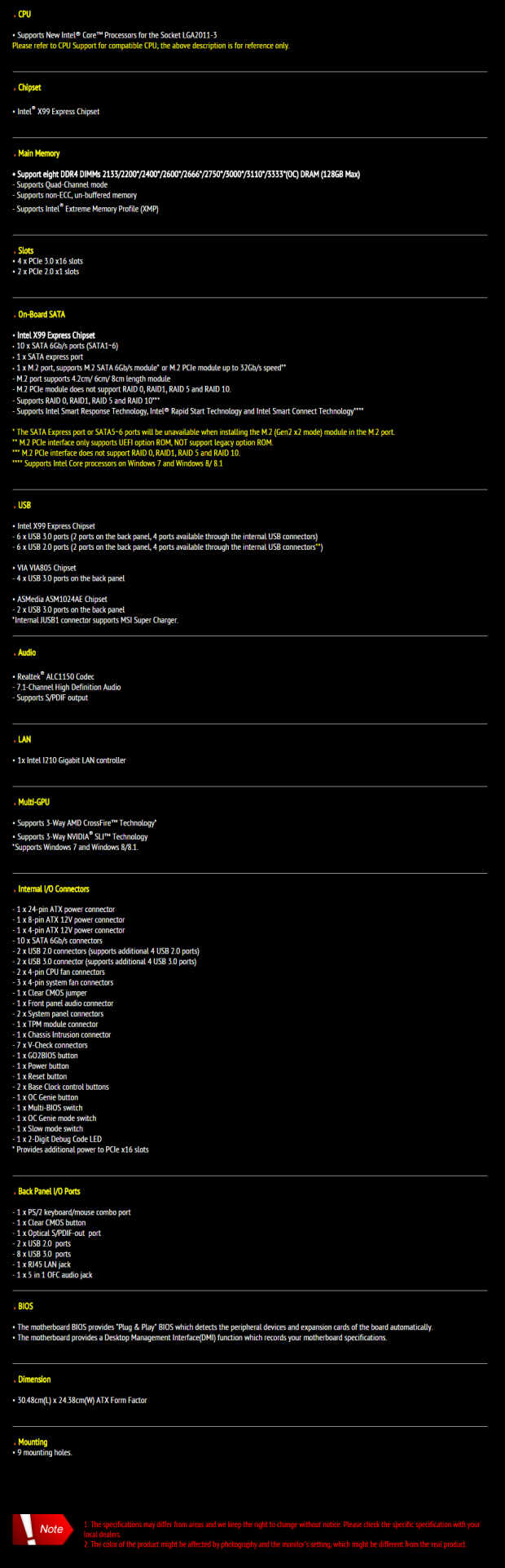
The most notable specification is that MSI decided to allocate 4x PCI-E 3.0 to their M.2 slot for maximum performance. They have also expanded the number of USB 3.0 ports and headers, and provided a nice set of overclocking features.
Pricing
At $285 on Newegg, the X99S-MPower is right in the middle between the most and least expensive X99 motherboards, of which there are many now.
It is targeted mainly at builders who want nice overclocks, and also entices overclockers looking to break world records.
PRICING: You can find the MSI Computer ATX DDR4 3000 LGA 2011-3 Motherboards X99S MPOWER for sale below. The prices listed are valid at the time of writing but can change at any time. Click the link to see the very latest pricing for the best deal.
Our Latest Socket LGA 2011 Review Coverage
United States: The MSI Computer ATX DDR4 3000 LGA 2011-3 Motherboards X99S MPOWER retails for $284.30 at Amazon.
Canada: The MSI Computer ATX DDR4 3000 LGA 2011-3 Motherboards X99S MPOWER retails for CDN$322.00 at Amazon Canada.
Packaging and the X99S-MPower
Packaging and the Board


The box is nicely designed and feels sturdy. The board is packaged inside in an anti-static bag and seems to be well protected.


The accessory package is very well done, perhaps one of the more interesting because of the extras MSI provides. MSI is giving away cool swag like a door tag, a plus sized case badge, and even a poster. Back to useful accessories; there are six SATA 6G cables, two SLI bridges, a back-panel IO shield, some header extensions, and cable stickers.


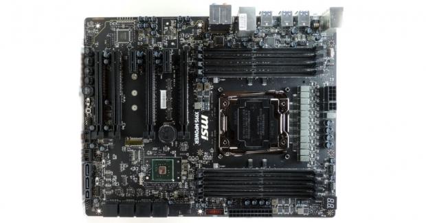
I have circled the fan headers on the board. There are a total of two PWM header and three voltage mode headers, all of them can be controlled by a really nice UEFI GUI or Windows software. The black and yellow accenting is subtle yet elegant; it is a very nice board to look at. The back of the board reveals some unprotected chips, but that shouldn't be much of an issue since they don't generate much heat and are low profile.
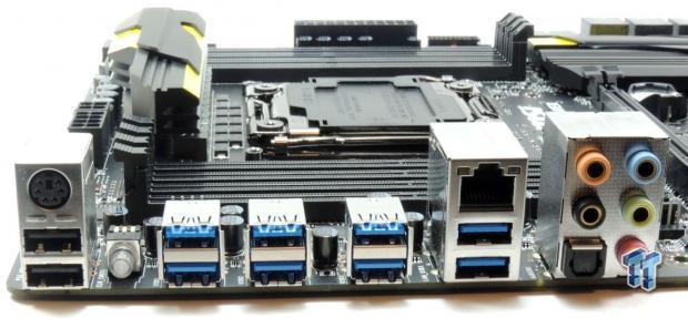
The back-panel IO features an Intel NIC, eight USB 3.0 ports, two USB 2.0 ports, a clear CMOS button, a PS/2 port, and a gold plated TOSLINK with S/PDIF optical.
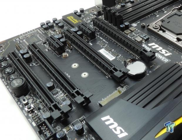
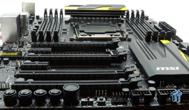
There are a total of four PCI-E 3.0 full sized 16x slots, but you can't run 4-way SLI/CF because of the extra PCI-E 3.0 allotment to the M.2 slot. If you run a single GPU or two GPUs, then the upper two slots are to be used for 16x/16x. If you do 3-way with a 28-lane CPU for 8x/8x/8x, you use the three uppermost slots and keep 4x for the M.2 slot.
If you do 3-way with a 40-lane CPU then you use the two uppermost slots and the last slot for 16x/16x/8x, but the M.2 slot defaults to 2x PCI-E 2.0 lanes from the PCH and shares bandwidth with the SATA Express connector.


MSI is known for their right angled USB 3.0 connectors, and they don't disappoint here. There are a total of 10 SATA 6G ports, two of them are shared with an SATA Express port.
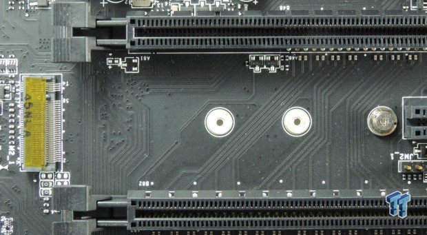
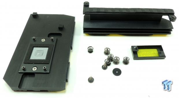
This is the M.2 slot that uses either 2x PCI-E 2.0 from the PCH or 4x PCI-E 3.0 from the CPU for 32Gb/s. You can actually chose which you want in the UEFI.
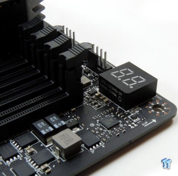
The POST code indicator is one of the handiest tools a system builder can have, and this one doubles as a digital CPU temperature display when the system is done with POST.
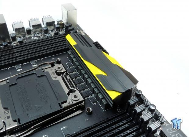
A long 12 phase VRM is being cooled by a hefty heat sink, we will cover it more detail in following sections.


The audio section is isolated from the rest of the motherboard PCB and there are LEDs on the underbelly of the board that will illuminate this path. MSI uses two amplifiers for the back-panel IO and front panel header audio outputs.
The heat sinks are held down by metal screws and make great contact with the components they cool.

MSI also provides overclocking buttons and switches. You can increase system parameters in real time, switch between 1.2GHz and a higher speed, or switch between different BIOSes very easily.
X99S-MPower Circuit Analysis
Circuit Analysis


This section will start off with a look at power regulation and then shift into general circuit selection and implementation.
CPU Regulator Analysis


The CPU VRM features a total of 12 phases, each phase is made up of an integrated power phase. The whole thing is controlled by a 6 phase digital PWM from Intersil. MSI is utilizing six ISL6617, which are phase doublers, to get 12 phases from the 6 the PWM provides. These phase doublers do a nice job of taking in one PWM signal and providing two. MSI is using 12x 330uF (3960uF total) tantalum capacitors, which have great properties when it comes to varying temperatures (like subzero). The inductors are MSI's SFC and should support up to 60A each. This is no doubt a strong arrangement.
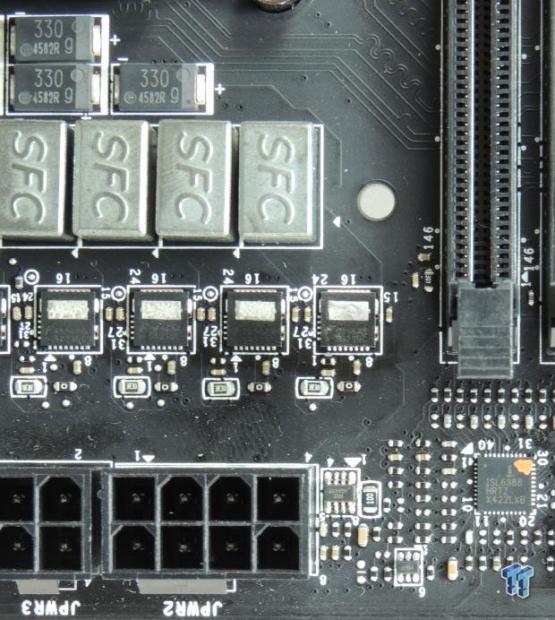
The power stages integrate one high-side and one low-side MOSFET along with a driver. These are from Fairchild Semiconductor. The FDMF5823DC are capable of outputting up to 55A each. They seem to also have an extra pad on the top, perhaps to act like a heat sink. The PWM is from Intersil, the ISL6388, and is Intersil's first digitally programmable PWM.
Memory Regulator Analysis


This is the first time I have seen a Powervation branded PWM used on a motherboard; they seem to be focused only on DC/DC buck controllers. MSI is using two of them here, one for each memory set. The PV3203 is a dual phase digital PWM. Each memory phase is made up of two ONSemi NTMFS4C05N and a single NTMFS4C08N, more than enough for the DRAM's main voltage rail.
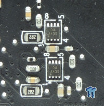
On the left, we have two drivers, there are two sets of these on the back of the board for both set of memory VRMs. On the right, we have an unknown chip, but it is most certainly in charge of PCH power.
General Circuit Analysis


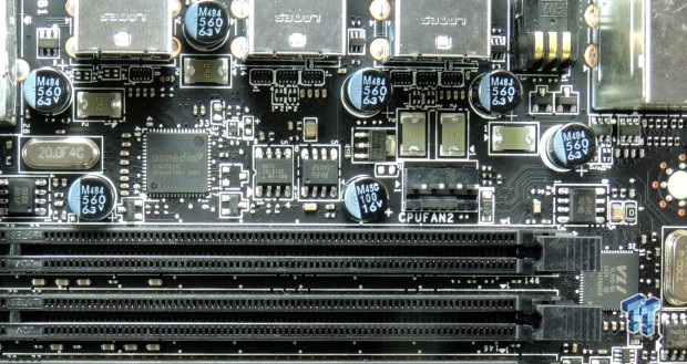
On the left, we have the audio codec the Realtek ALC1150 exposed without its cover. An LED illuminates the Audio Boost logo when the system is powered on. One of the Texas Instruments OP1652 is visible as is an LPC812 chip which is a 32-bit microcontroller. On the right, we have an Intel WGI210AT, which is a well-known Intel NIC.
Both USB 3.0 controllers can be found here. Each one gets a single lane from the PCH. The ASMedia ASM1042 provides two USB 3.0 ports, and the VLI VL805 provides four USB 3.0 ports.
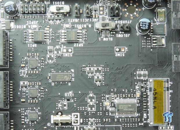
MSI is switching PCI-E lanes from the CPU and PCH to the M.2 and SATA Express ports. This has to be implemented with care and MSI seems to have done a sound job with the addition of two ASM1467, which are PCI-E re-drivers for the M.2. Re-drivers help extend signals or reinforce them in crowded circuits. The two Winbond 128Mbit BIOS ROMs can also be found here as well as a nuvoTon NCT5605 which is a GPIO used to expand OC features.


In the two images above, there are four identical ASM1464's, these are USB 3.0 re-drivers to help ensure very fast USB 3.0 speeds. I wanted to make sure to cover these as not many manufacturers put in this much effort into signal quality for USB.
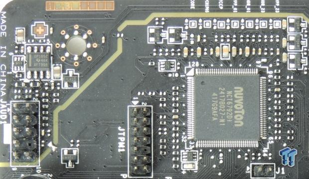
The nuvoTon NCT6792D is a common Super IO, it handles all the temperature, voltage, and fan monitoring and control. It also provides the PS/2 port on the back-panel IO. The second OP1652 audio amplifier can be seen here near the front panel header which it is connected to.


Pericom PCI-E 3.0 quick switches can each move two lanes; they are plentiful on the X99S-MPower because of the unique design of the M.2 and PCI-E slots.
BIOS and Software
BIOS
MSI's BIOS is one of the most fine-tuned I have seen for general use. I am a fan of their new UEFI especially of the fan control.
I really like how the board recovers from a bad overclock, prompting you with many options before you even get into the UEFI. There are also UEFI profiles for overclocking, but watch out as the LN2 profile will disable some peripherals like audio and LAN. All in all, the UEFI is very well done.


Software
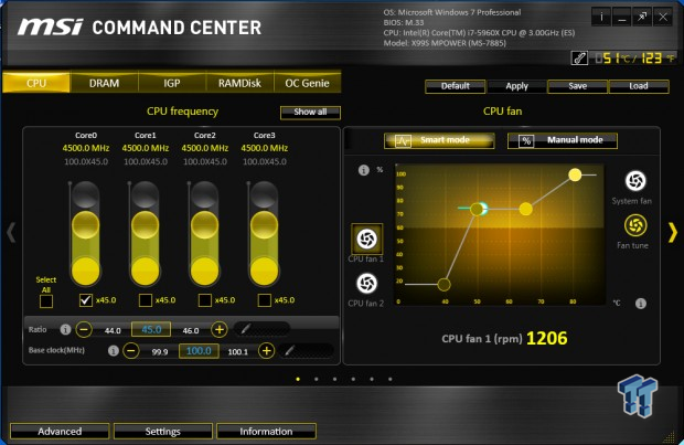
This is MSI's Command Center, which is a very versatile and loaded piece of software to control overclocking parameters, fan control, and a RAM Disk.


MSI's ECO center is aimed at controlling power distribution to the board to keep things power friendly. MSI also has a customized skin for the Realtek audio codec.
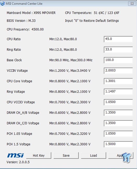

MSI also has two pieces of software for quick overclocking, they are lightweight which makes them perfect for high stakes low stability overclocks.
Test Setup and Overclocking
Test Setup
A big thanks to Corsair for sponsoring the case, fans, SSD, USB drive, and PSU!
A big thanks to Seek for sponsoring the Thermal Camera. You can find my review of the camera here.
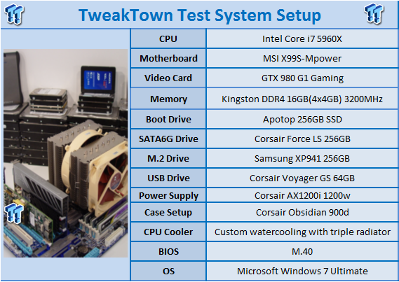
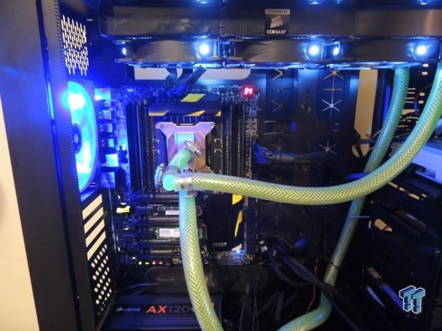
This is the new test bench, and it is designed to test every aspect of the motherboard and it's IO. I have designed it so that the motherboard sits in a case and is cooled by fans always on at a constant rate to keep the conditions similar for all tests. I have cut out part of the case behind the motherboard so I can get thermal images of the back of the PCB where the VRM heat spreads. System and CPU power measurements are now digitally logged. We are also using a Netgear Nighthawk X4 AC2350 for our Wireless AC tests. The latest M.2, SSD, and USB technologies are also being utilized to test the maximum potential of the motherboards that are being tested.
Overclocking Results
CPU Overclocking
Max CPU Overclock is found by setting the VCore to 1.5v, Input voltage to 2.1v, cache voltage to 1.2v, CPU multiplier to 45x, memory and cache multipliers to 12x, and disable any features that would result in CPU frequency fluctuation. I then proceed into Windows and use software to increase the multiplier.
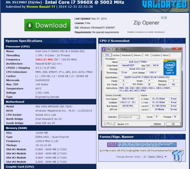
5.0GHz is the maximum of our CPU on this board.
Maximum AIDA64 Stable Overclock (BIOS settings below for this):
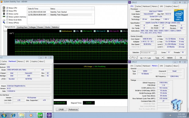
I was easily able to pull off 4.5GHz on the CPU with 3.3GHz Cache and a 2400MHz overclock on my memory manually tuning the UEFI.
CPU, Memory, and System Benchmarks
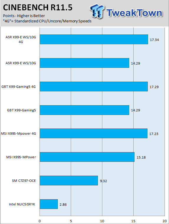
CINEBENCH 11.5
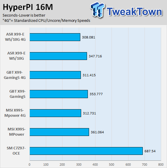
HyperPI
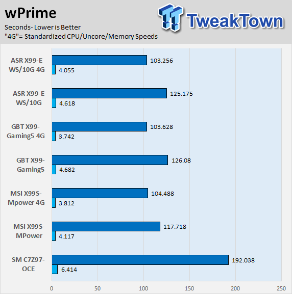
wPrime
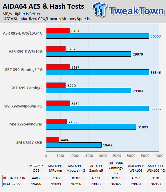
AIDA64 AES and HASH
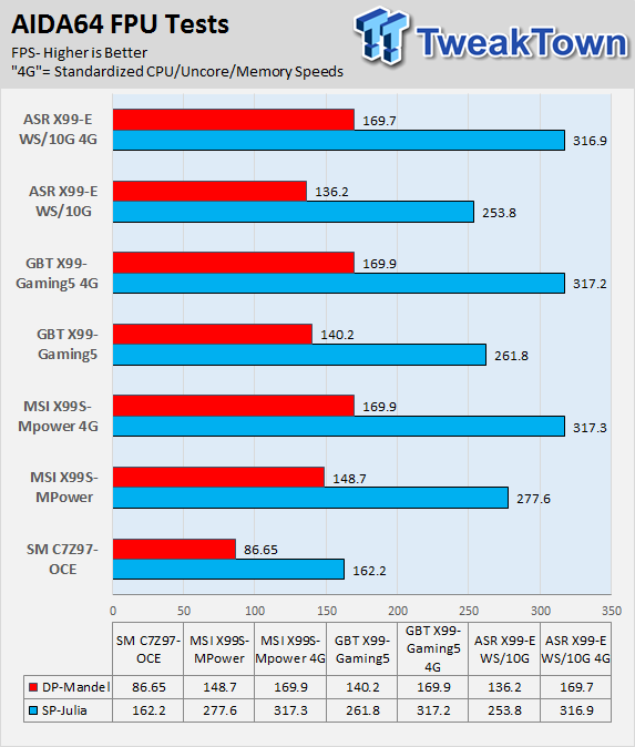
AIDA64 FPU
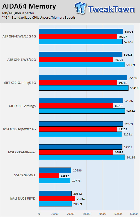
AIDA64 Memory
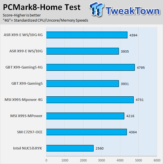
PCMark8 Home Test
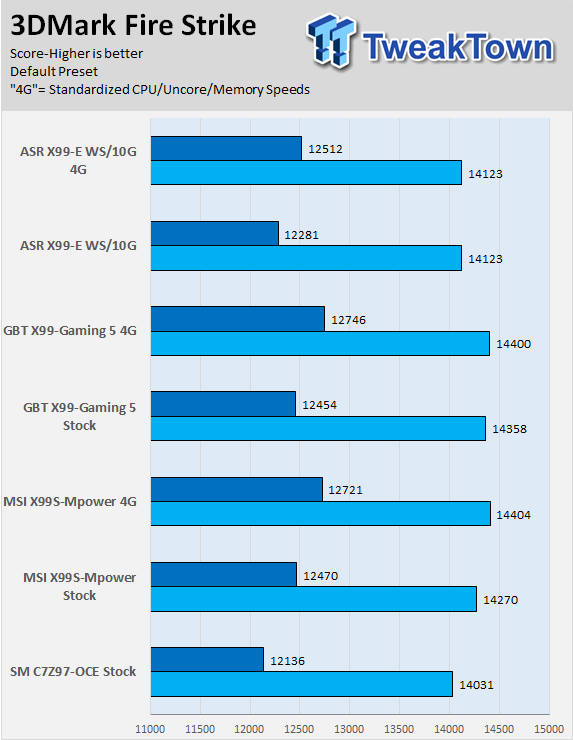
3DMark: Fire Strike
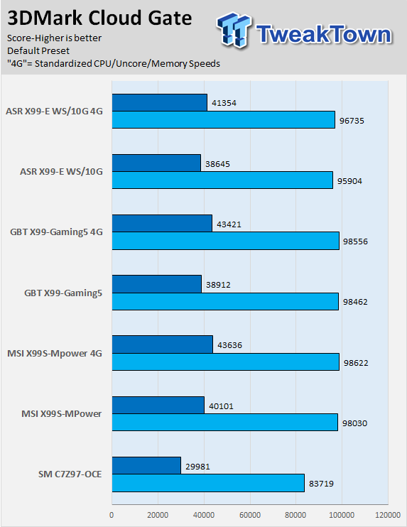
3DMark: Cloud Gate
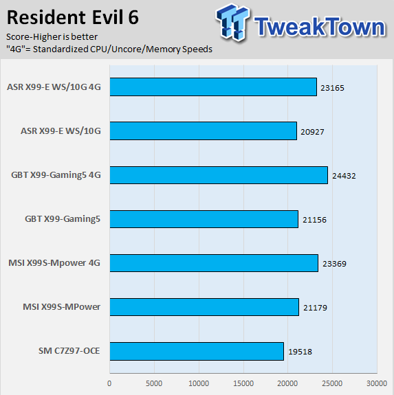
Resident Evil 6
System IO Benchmarks
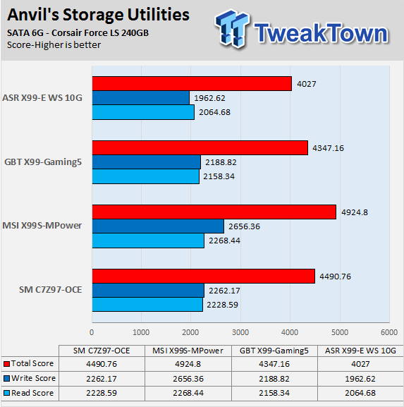
Anvil SATA6G:
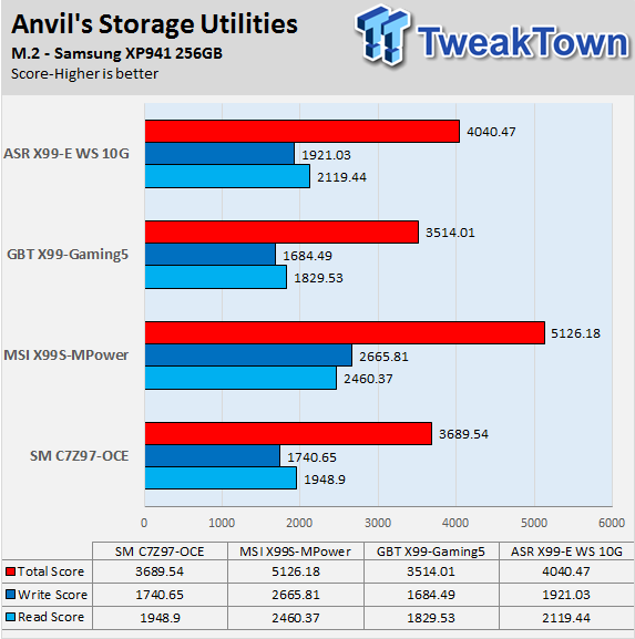
Anvil M.2:
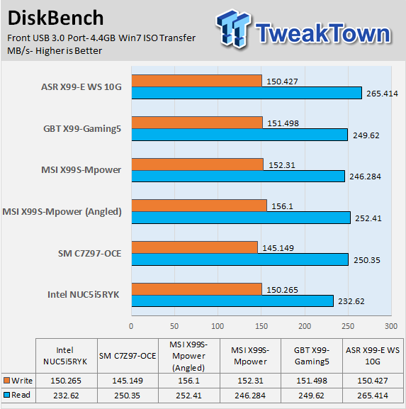
Diskbench USB 3.0:
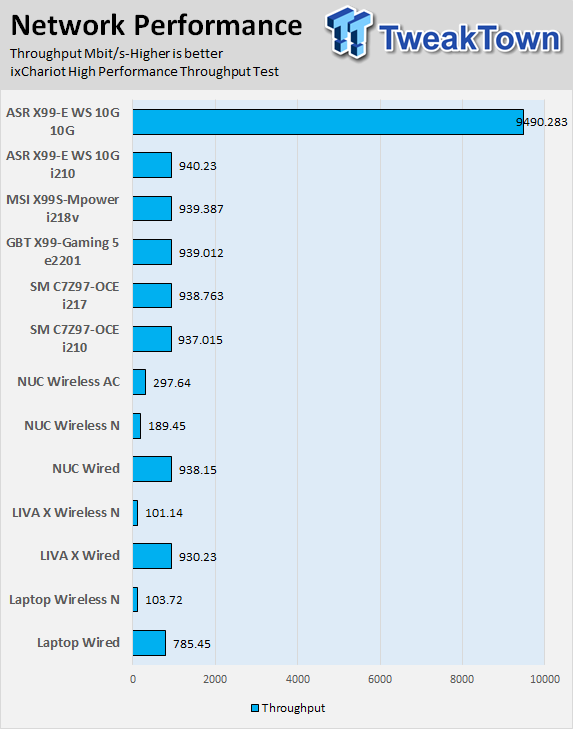
ixChariot Network Throughput:
Audio RMAA 5.5:
I disable all audio features set the correct bitrates and then test the audio with a loopback test.
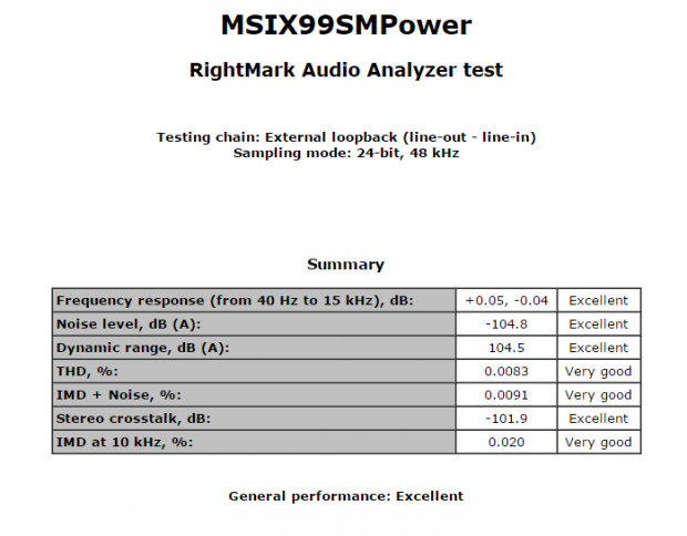
Sound Judgment by Ear: Very Good.
There are 5 ratings for audio: 1. Problems, 2. Okay, 3. Acceptable, 4. Very good, 5. Excellent
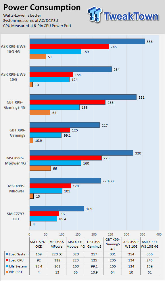
Temperature and Power Consumption
System power usage is measured at the AC/DC PSU (the AX1200i) which I have connected to another system to measure the test system and as a backup I have a wall meter to verify. The CPU power is measured through the 8-pin connect which is hooked up to a hall effect IC which measures current and puts out a voltage in proportion to the current. That voltage is logged by a National Instruments ADC which logs the DC voltage level, which I then convert into current.
Note on Thermal Images: In the temperature section we use our Seek thermal imaging camera to capture the surface temperatures of major components on the board; I look at the VRM and then all other things that light up the screen. If there is something to worry about then I will state it, otherwise I will just show the hotter running parts of the board for fun. Unless some component is over 80-90C then there really isn't anything to worry about.
All systems will act differently, so I will look for commonalities, such as how far from the VRM the heat spreads through the PCB and the difference in temperature between the PCB and the chokes. Keep in mind that the majority of the heat from the VRM goes into the PCB as it is a giant soldered on copper heat sink.


These were taken at stock speeds, on the left while idle and on the right while loaded.


On the left are two chokes that lit up, when the system is totally at idle the PWM only turns on two phases. The right is the backside of the PCB with no load, and a small amount of heat can be seen on the opposite side of the back where those two phases are.


These images were taken at stock speed, but at full load. On the left are the chokes and on the right is the back of the VRM. The VRM is doing its job and the heat sink seems to be doing its job as well, heat is evenly spread and a bit stronger towards the center where it goes to the CPU. There is a little light up near the right side on the back; that is because the PWM chip is working and gets a little warm (totally normal).


These pictures were taken at 4.5GHz full load. 50C/52C are pretty good temperatures for such a big VRM at load.


I thought you guys might want to see how hot the memory VRM gets. As you can see, it doesn't get too hot, but it's cool to see the difference load makes on the MOSFETs.
Final Thoughts
A few months back, I had written an overclocking report on the X99S-MPower, and I was very impressed by the board. It offered good overclocking performance and a solid UEFI to match it.
Performance wise, it keeps up with other boards in the performance category; however, where it really shines is storage. The highest M.2 and SATA 6G scores are taken by the MSI X99S-MPower. I did expect as much since MSI used re-drivers to make sure the signal quality stays high.
MSI also did a very nice job at ensuring that conflicts between devices stay low, it's possibly one of the only boards I tested where I didn't have to do much tinkering to get the system to boot to my boot drive. The one thing that could be improved is the spacing for SLI/CF; also 3-way performance comes at a price, especially if you use an M.2 drive.
I am finally able to see what I predict from my VRM analysis, I am able to see the PWM turn off all phases except two. In this case, those two are on the same PWM phase, so it can't just sit on 1 phase. The board runs very cool on idle and at full load temperatures are very acceptable. It is nice to see a product perform as the manufacturer promises; the X99S-MPower is a well-rounded product.
At $285, the X99S-MPower is considered a mid-range X99 motherboard, yet is a high performance product. It boasts some of the same features as more expensive boards, and will provide strong 24/7 overclocks for anyone in the market for an affordable yet well-executed motherboard.
PRICING: You can find the MSI Computer ATX DDR4 3000 LGA 2011-3 Motherboards X99S MPOWER for sale below. The prices listed are valid at the time of writing but can change at any time. Click the link to see the very latest pricing for the best deal.
United States: The MSI Computer ATX DDR4 3000 LGA 2011-3 Motherboards X99S MPOWER retails for $284.30 at Amazon.
Canada: The MSI Computer ATX DDR4 3000 LGA 2011-3 Motherboards X99S MPOWER retails for CDN$322.00 at Amazon Canada.
 ASRock Z890 Taichi Aqua Motherboard Review - Flagship features without the flagship price
 GIGABYTE Z890I AORUS Ultra Motherboard Review - Mini-ITX with surprisingly good thermals
 GIGABYTE Z890 AORUS Elite WiFi7 Plus Motherboard Review - Right in the sweet spot
 ASUS ROG Strix X870E-E Gaming WiFi7 NEO - A Crosshair by any other name
 MSI MAG B850 Tomahawk Max WiFi II Motherboard Review - Leveling up
 Apple's first touchscreen MacBook Pro is '100% confirmed', leaker says
 AMD reversed a warranty rejection for a swollen Ryzen 9 7950X3D after Hardware Unboxed called it out publicly
 ASUS' $50 ROG Equalizer cable meant to stop GPU connector burns reportedly burns itself
 Intel's 18-core Core Ultra 7 251HX is matching its 20-core siblings in early PassMark results
 Elon Musk is the world's first trillionaire - enough to spend $1 million a day for nearly 3,000 years
 Anthropic's latest AI model 'Fable' was so powerful the US government banned the world from it
 Xbox prioritizes Elder Scrolls VI, Fallout, and Halo in new strategy shift
 Xbox exec wants to use ads to open up new access points, not just to collect money
 Redditor buys RTX 2080 Ti Super engineering sample on eBay, has the same number of cores as an RTX Titan but half the VRAM
 Report: Xbox may be spun off into subsidiary or joint venture with another company
 MOAIPLAY ORA PRO G1 850W ATX 3.1 PSU Review: high efficiency and 10-year warranty for $119.99
 Navman MiVue Smart True 4K Surround Dashcam Review - Seeing In All Directions At Once
 IQUNIX Magi96 Pro Aluminum Low Profile Mechanical Keyboard Review - Premium Build, Satisfying Sound
 Asetek Forte S-Series Racing Simulator Bundle Review
 Razer Pro Type Ergo Wireless Split Ergonomic Keyboard Review - Built for Comfort and Support
 ASUS ROG Strix Morph 96 Wireless Gaming Keyboard Review - Great Performance, More Affordable
 SAPPHIRE Radeon RX 9070 GRE PULSE OC Review - A New 1440p Challenger Has Arrived
 NZXT H6 RGB+ Compact Dual-Chamber Chassis Review
 ASRock Radeon RX 9070 GRE Steel Legend Review - The RDNA 4 Mid-Range Reshuffle
 This Windows security feature protects Documents from ransomware, but it is off by default
 Windows 11 already has a voice typing tool, and it is the one most people are not using
 Quick Assist is the only remote-support tool I open when a relative calls about their PC
 The PowerToys utilities I keep enabled on every Windows 11 PC, and the ones I turned off within a week
 TweakTown's Best of Computex 2026 Awards - The Best Hardware, Gaming Gear, and AI
 Phison E37T SSD Controller Exclusive Preview - The Fastest DRAMless SSD Platform Yet
 USB Ports Not Working in Windows 11? Try These Fixes
 ASUS WiFi Routers and Networking Solutions Deliver Long-term Security and Reliability with No Additional Cost
 Second Monitor Not Detected in Windows 11? Try These Fixes
 Turn Your Old Smartphone Into a Dedicated Webcam for Your Windows PC