


Introduction
Heatsink technology has rapidly improved over the last few years. The introduction of heatpipes, use of large radius fans and the sophisticated mounting mechanisms have all aided these developments. One area that has remained unchanged is the way these products are tested. The old way has proven to be inaccurate, unreliable and careless for comparing one heatsink to another. Luckily things are about to change for consumers looking to find accurate performance information that scales across all of TweakTown's CPU heatsink tests.
Intel and AMD are currently in a battle to reduce their mainstream processors power usage and heat output. Enthusiast products such as the FX and Extreme lines seem to be exempt from the trend and have been increasing steadily. Overclockers have always looked to push their thermal envelope, sometimes reaching 250 watts of heat output when using phase change cooling units.
With this amount of heat output companies were required to produce heatsinks which could handle the additional load. Traditionally the answer has been to produce larger products but this has proven to be unacceptable because more copper and aluminum increases costs. The latest trend has been to collect the heat with pipes filled with fluid and move it to an area where larger fans can remove the heat. Processor heatsink fans started out at around 40mm many years ago and now 90mm and 120mm are becoming normal.
Even though processors and their cooling devices have evolved, the way in which they are tested has stayed the same for many years. Up to this point reviews have stuck to placing a cooling product on a CPU attached to a motherboard and use unreliable sensors to measure performance. Not only are the sensors unreliable but testing environments are uncontrolled as well. The air surrounding a heatsink plays as much of a part in the cooling device's performance as unit construction does, in some cases more so. This lack of control makes for careless evaluations since the performance can change not only day to day but even hour to hour. If you are trying to determine performance between multiple products then the old way is as accurate as rolling the dice.
Today we are going to introduce our readers to a new method of CPU heatsink testing and show how the system works by testing a pair of retail AMD and Intel heatsinks that will be used as a baseline for all forth coming processor reviews. To show the accuracy of the tests, these products were tested at different times of different days with different room ambient temperatures.
Methodology and Construction
Methodology
There are actually two parts of a system that need to be controlled. The processor must have reliable heat output at full, middle and idle loads while the air surrounding the heatsink must also remain a constant temperature. Our new system meets both of these requirements and does so within 1 degree Celsius.
Construction (The CPU Die Simulator)

An AMD Opteron socket 940 processor will donate us its heat spreader for the project.

The next step is turning this block of copper into a simulated processor.

Just placing the heat spreader on the block is not going to work.

Here you can see the processor without the heat spreader. The IHS contacts the processor by the die. This is also where the heat comes from. Along the edges of the HIS a glue is applied which keeps the two in contact and also acts as an insulator.

The IHS also has a lip on its edges. The CPU die uses a thermal interface material (TIM) to help move heat from Point A to Point B.

To make the testing go like we want the size of the CPU die must first be carved out of the copper block. Off to the machine shop we go.

This is our simulated CPU after it was returned from the machine shop. It has been machined exactly to the specifications of the Opteron except the die is a centimeter taller to allow us to match the exact height of an AMD socket AM2 processor.

In this image you can see how the system is starting to come together. A PCB was used to simulate a motherboard.
Construction - Continued
Construction (The CPU Die Simulator) - Continued

This is the heating and height adjustment area. Since AMD and Intel have different processor heights the bottom copper block can be changed with another piece that gives the simulated CPU the exact heights for Intel testing.
In this image you can also see the holes drilled for measuring the temperature of the simulated die. On the first trip to the machine shop I forgot to include this in my AutoCAD drawing. I tried to make the hole at home but quickly learned that a professional was needed. The machine shop was able to drill a hole all the way down to the middle of the die, a feat that is much harder than it looks even with a drill press and new drill bits.

In this image the Intel copper block has replaced the AMD block giving us the exact height of an Intel processor. You can also see the black tape that was built up to balance the IHS to the simulated CPU die. All of the parts were also coated with thermal paste, Arctic Silver 5 was used between the die and the IHS and peltier used as a heat source. Ceramique was used to attach the cold side of the peltier to the height blocks since it is effective at sub 0C temperatures.

The first mounting of the system to the internal wiring box, it might look ghetto now but read on.

The final revision of the box with both AMD AM2 mounting and Intel Socket 775 holes drilled into the PCB. All of the wiring has also been routed to spring loaded quick disconnect speaker plugs for easy installation into other upcoming simulated products.
Construction (The TECC, Thermal Environment Control Chamber)
Since incubation chambers can cost many thousands of dollars we needed to make an affordable solution that can keep the temperature inside at a perfect 40 degrees C.

An 8 foot by 4 foot sheet of Dow Corning Foam Insulation was used for the construction of our Thermal Environment Control Chamber. To minimize the need for additional material which would raise costs, a 2 inch thick piece was used for construction. The product has an R rating of 10 (R10) at 2 inches.

After cutting four 36 inch by 24 inch sheets the chamber started to take shape. I used 6 inch nails with Liquid Nail to attach and seal the enclosure.

The entire Dow Corning foam was used in the construction of the box. This is the finished box without the door attached and without the electronics installed.

In this shot you can see the door installed and the electronics starting to make their way into place.
Setting Up the Electronics and Sensors
Construction of Electronics and Sensors
The TECC box needs to be heated to resemble a modern PC case, but the system must also be controllable too.

The TECC uses six 20 watt halogen lamps for lighting and to raise the temperature of the sealed box to 40C. Their intensity can be raised or lowered with a control panel to keep the system at the correct temperature.

Our thermal measurement device is shown here. This is the system with the door panel off at room temperature. The top number is the ambient box and the middle number is our die simulator. The bottom number is the humidity as measured inches away from the heatsink on the incoming air side.

The peltier and the CPU fan are powered by a Meanwell 320 watt power supply designed for this type of work. By adjusting the voltage to the peltier to 9.5 volts and the CPU fan to 7 volts we can simulate an idle load. When these are raised to 12 volts for both items we can simulate the system running at full load.

The acoustics are measured through a ½ inch hole in the foam. This puts the Sound Pressure Level Meter (SPL) at 14 inches away from the simulated processor die. Most heatsink manufacturers quote their ratings at 1 meter so our numbers will be much higher than the fans rating. On the other hand the ratings will be accurate when compared to other products.

Attached to the CPU Die Simulator box is a small PCB that holds the humidity and ambient air sensor. This is located less than 6 inches from the CPU die.
Testing Procedures and Products
Testing Procedures
Since we are trying to normalize the entire testing processes we are not going to let something like thermal paste derail us. I have learned that the thermal paste included from heat sink manufacturers can affect the results by as much as 3C. To eliminate this, all CPU coolers will be tested with the enthusiast standard; Arctic Silver 5, this regardless of what brand or type TIM is provided with the sample.

The Enthusiast Standard, Arctic Silver 5

The same amount of AS5 will be applied for all of the cooling reviews. A "dot" will be made in the center of the IHS that will then be spread by the pressure applied from the heat sink. Many enthusiasts use this method and I enjoy it myself.

In this shot you can see a retail Intel CPU Heatsink is in perfect contact with the simulated CPU. Since the height is the same as a retail motherboard with an actual processor installed the PCB has a little curve from the pressure exerted by the heatsink, just like a motherboard.
Creating a Baseline for all Others to Follow: It is important to check for a nice balance to ensure that your methodology is working the way it was designed. For this first series of performance results the tests were conducted over several days at different times and with different room ambient temperatures. I am very excited to say that the results of all tests were within .1C of each other!
Test Products
The first two heatsinks we are going to test in our new system come from AMD and Intel. Both of these companies ship several different heatsinks that are produced by OEM companies. None of these heatsinks have a "retail" name outside of the company so we used two that were on hand.

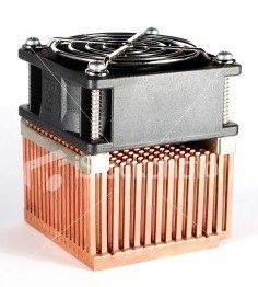
Our test Intel (Left) and AMD (right) OEM heatsinks. In this side view you can see the way the base of the AMD heatsink is constructed and the Intel fins.

A view from the top shows the difference between the fan types used on the coolers.

The side view shows the way the fans are mounted to the heat sink.

Our last image here shows the copper and aluminum bases used for the two OEM coolers.
Test Results and Conclusion
Testing
Using the methods we've explained earlier, we tested the two OEM coolers.

An image taken during the first test session during setup.
Results
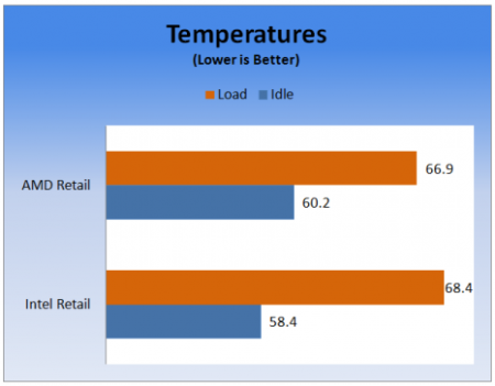
Temperature measured in Celcius, lower is better
At idle our two OEM coolers performed 18.4 and 20.2 Celsius warmer than the ambient air. At full load the numbers increased as they should to 26.9 and 28.4 C over ambient. I was surprised that the all aluminum AMD cooler performed better under load than the Intel cooler. It does appear however that the use of copper on the Intel cooler does help it stay cooler at idle.
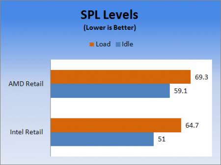
Sound Pressure Level measured in decibels (db), lower is better
The acoustic tests caught me by surprise. I knew that the Intel coolers use an onboard thermal probe to adjust the fan speed based on ambient temperature but I was unaware that AMD uses a similar system. Because of this, testing for acoustics must be performed at the same time as the temperature testing; simply pushing 7 and 12 volts through the fans will not produce an accurate measurement.
Conclusion
The pavement has been laid and a blueprint for accurately evaluating the performance of CPU coolers is now set. Next week the first round of retail CPU coolers will make their way through the Thermal Environment Control Chamber and we will begin our quest to find the best air coolers available on the market.
 Lian Li B4-mATX Review: a compact mATX SFF case with excellent airflow and premium features
 Ocypus Sigma F36 BK ARGB Cooling Fan Review: high airflow and unified design in one frame
 PCCooler CPS RZ820 Display Review: a flagship-level CPU air cooler with an LCD screen
 MOAIPLAY ORA PRO G1 850W ATX 3.1 PSU Review: high efficiency and 10-year warranty for $119.99
 NZXT H6 RGB+ Compact Dual-Chamber Chassis Review
 Razer unveils Wuthering Waves collection with a custom keyboard, mouse, and premium gaming chair
 Intel prepping Ryzen X3D rivals with new 22-core Nova Lake-S CPUs with 108MB of cache for PC gaming
 Lenovo starts shipping laptops with Chinese-made YMTC SSDs due to skyrocketing NAND Flash prices
 Gen Z would like esports and professional gaming taught in school, study finds
 OpenAI sued after man says ChatGPT fed his religious delusions before suicide attempt
 First Steam Machine spotted with 'red line of death' after playing No Man's Sky for 20 minutes
 Google unveils Android Halo, the new home for AI agent living in your smartphone
 This $6 indie is the best-selling game of 2026, beating major AAA releases
 Halo CE remake's LASO playlist clarified by Halo Studios
 Hideo Kojima mourns loss of PlayStation game discs, warns of streaming-only future
 The Super Mario Galaxy Movie (2026) 4K Ultra HD Blu-ray Review
 KTC H49S66 5K2K (5120x1440) 49-inch 180Hz Gaming Monitor Review
 HighPoint Rocket 1604L Gen5 x16 NVMe Software RAID AIC Review: half the price with full 59 GB/s speed
 Next Level Racing ERS3 Haptic Seat Review: immersive sim racing comfort with integrated haptics
 ASUS TUF Gaming X870-Pro WiFi7 W NEO Review - Tuffed up
 GIGABYTE GO27Q24G Gaming Monitor Review: Glossy OLED Gaming at 240Hz
 MSI MPG 322UR QD-OLED X24 Review: A Brighter, Tougher 4K 240Hz QD-OLED for $1099
 UGREEN NASync DXP4800 GT Review: powerful 4-bay NAS with AMD Ryzen and dual 10GbE ports
 Dell XPS 14 (2026) Laptop Review - Premium Quality, Impressive Performance
 How to Remap Keyboard Keys in Windows using Microsoft PowerToys
 7 tips to organize your Windows files for faster, easier access
 Intel Arc G3 Extreme first impressions with MSI's Claw 8 EX AI+ - Incredible power for an extreme price
 How to fix Wi-Fi Adapter Not Working on Windows laptops: troubleshooting tips
 Hisense U7SG 4K TV: Modern Entertainment for the New Age
 6 underrated Microsoft Word features worth using to boost your productivity
 Level Up Your PC Gaming with these Fantastic ASUS Prime Day Deals on GPUs, Motherboards, and More
 GIGABYTE Wants to Kickstart Your New Gaming PC or Upgrade with These Limited-Time Deals
 7 Windows settings to change right after installation for better privacy, security, and performance
 I stopped Windows 11 notifications from interrupting me with Do Not Disturb, Focus, and a priority list