The Bottom Line
Introduction, Specifications, and Pricing
GIGABYTE has one of the largest Intel X99 motherboard fleets in the retail market. Instead of leaving just a few models to satisfy their customers, they tend to tailor their segments to better target their end users' needs. GIGABYTE has come out with G1 Gaming, SOC Overclocking, and Ultra Durable lines. While each type of board is specifically targeted towards gamers, overclockers, or power users, all the boards cross over into each other's domains.
Their overclocking boards carry upgraded audio and their gaming boards carry overclocking features, while their main series carries both. Today, I will look at one of GIGABYTE's main series Ultra Durable motherboards, the X99-SLI. While I usually cover high-end products, most users try to purchase the least expensive motherboard that can handle what they need. Let's see if the X99-SLI is up to the task of running a flagship processor, and pushing it to its limits.
Specifications
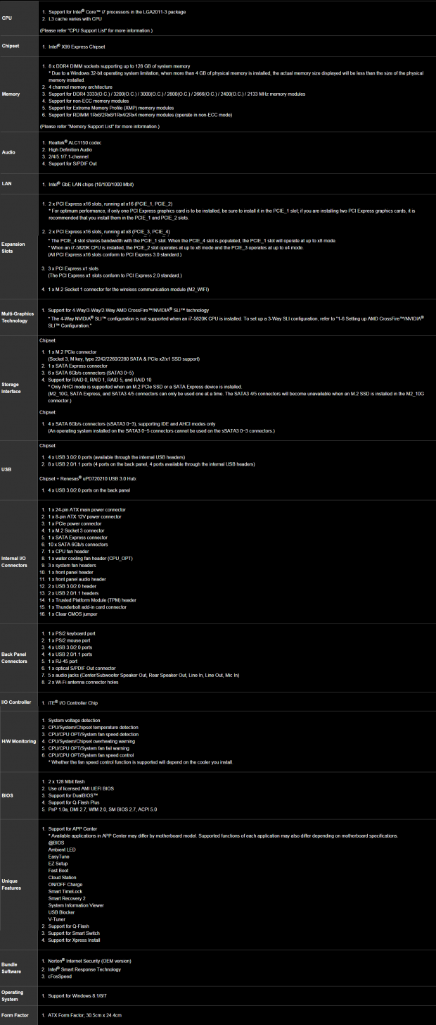
The specifications of the X99-SLI are almost identical to that of the X99-UD4P ($20 more) which I have not reviewed. The only real differences I could find is that the UD4P has an IO shield and heat sinks with built in LEDs, and the UD4P is E-ATX while the SLI is ATX. The X99-SLI is inherently a "basic" X99 motherboard when it comes to connectivity, in that all the PCH features are being utilized, and third-party controllers are rare. The board does have a lot of advanced, non-connectivity, features like USB BIOS recovery, Dual BIOS, and GIGABYTE's increased pin count socket.
Pricing
The X99-SLI is $240 on Newegg and $255 on Amazon at the time of this review, which is in the low-middle range for X99 motherboards.
Packaging and the X99-SLI
Packaging and the Board
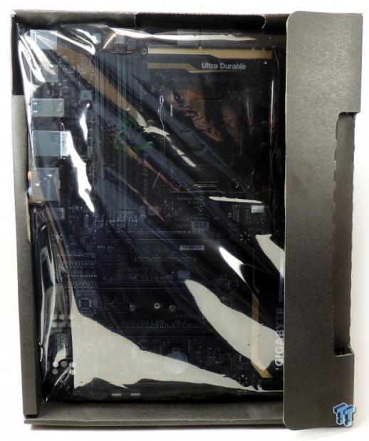
The box is simple and the packaging is well done. The board is in an anti-static bag in its own mini-box.
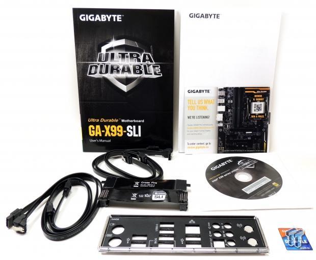
Accessories include 4x SATA6G cables, IO shield, 2-Way SLI bridge, 2-way CrossFireX bridge, driver DVD, manuals, and GIGABYTE sticker. There is also a little form that asks buyers to give GIGABYTE direct feedback on their product for the chance to win a free BRIX, a nice gesture.
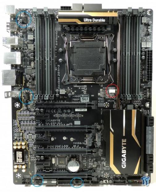
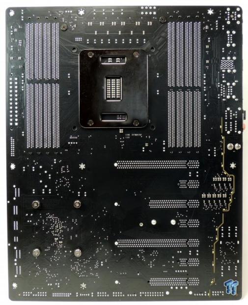
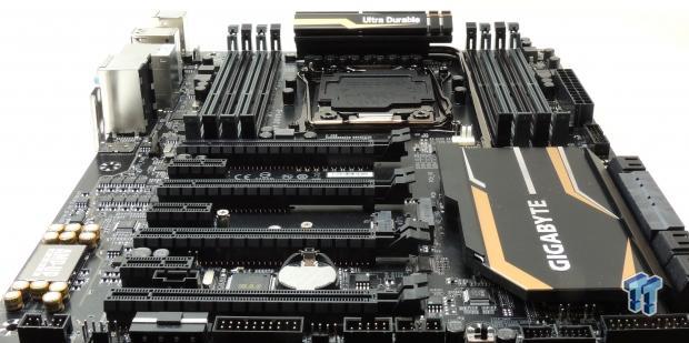
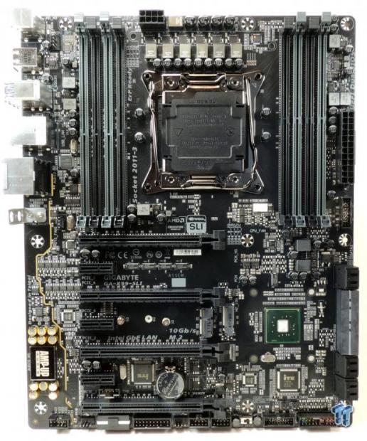
I have circled the five fan headers in red and blue. The single CPU fan header circled in red is for PWM fans, and the rest of the four headers are voltage mode fan headers. The fan headers do seem to be located towards the left side of the motherboard. There are gold accents on the board, and they aren't overwhelming, but they can be hard to match with other case accessories. GIGABYTE has darkened the color of the PCB markings, so that they are no longer white, but rather gray so they don't stand out as much. The back of the PCB is bare except for a few LEDs for the audio PCB divide.
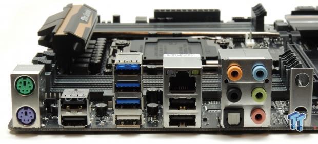
The IO Panel features only 4x USB 3.0 (white port is for USB BIOS recovery), 4x USB 2.0, PS/2 Keyboard and Mouse ports, RJ-45 1GBit LAN, a TOSLINK with S/PDIF, and a bracket in case you want to install an M.2 WIFI card.
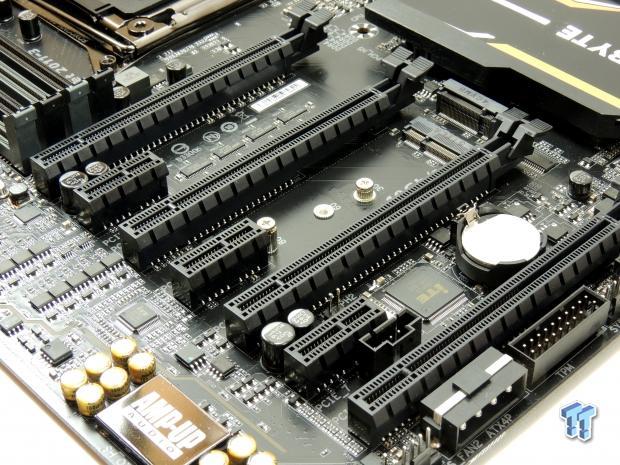
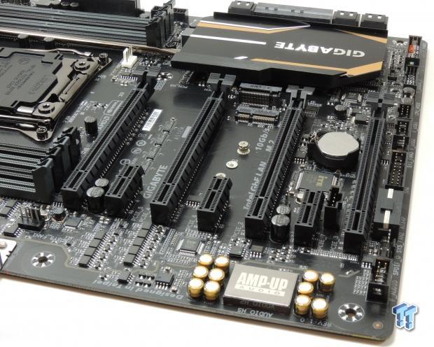
The PCI-E layout on this motherboard is optimized for multi-GPU configurations. All the PCI-E bandwidth from the CPU reaches the slots, and does so almost without delay. The third and fourth slots are hardwired at 16x (third slot) and 8x (fourth slot). The first slot has its first 8x hard wired to the CPU and the second 8x can be shared with the second PCI-E slot if needed.
A MOLEX receptacle for extra PCI-E power is provided at the bottom of the motherboard and both M.2 slots are between the second and third PCI-E 16x slots. There are two M.2 slots. The upper M.2 slot shares its bandwidth with the SATA Express port and its two SATA ports. The lower M.2 slot is for WIFI/BT M.2 cards, which are different than M.2 SSDs. All the PCI-E 1x slots are directly routed to the PCH.
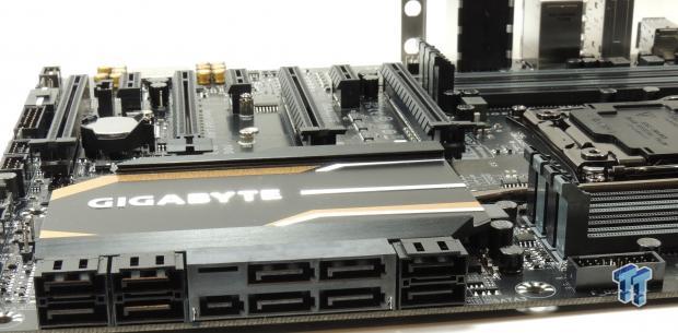
GIGABYTE equipped the X99-SLI with 10 SATA ports, two of which are shared with the SATA Express and M.2 ports. The four ports labeled sSATA cannot do RAID, while the other six can. A USB 3.0 internal header is positioned below the 24-pin connector. This board has a second USB 3.0 internal header located at the bottom of the motherboard as well.
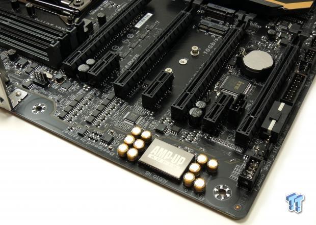
The audio on the X99-SLI is powered by a Realtek controller under an EMI shield. The PCB is physically divided to isolate the audio's analog domain from the rest of the motherboard. There is also a single amplifier for the backpanel port and some Nichicon audio capacitors.
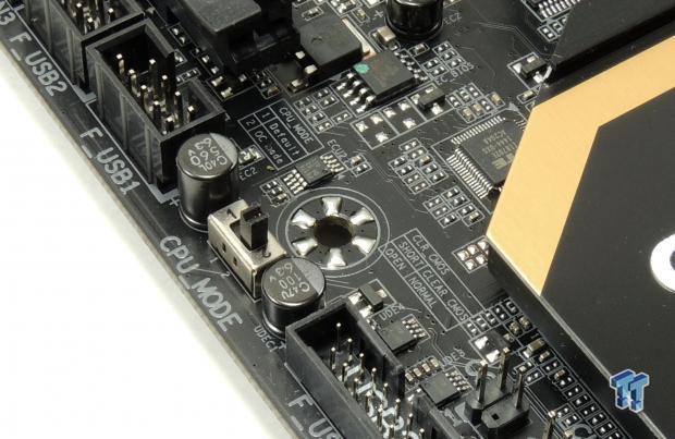
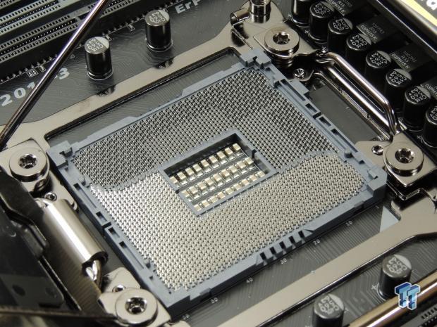
The CPU mode switch allows for users to enable the extra pins in the socket. The CPU socket has extra pins compared to the standard LGA2011-V3 socket. These extra pins allow for a higher cache ratio overclock (uncore) and for a lower IMC voltage, which can lead to higher memory overclocks.
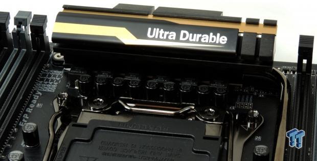
The VRM is made up of 6 phases, and it's the same as the VRM found on the X99-Gaming 5P and other 6-phase GIGABYTE X99 motherboards. While it might not seem like much, it is more than enough.
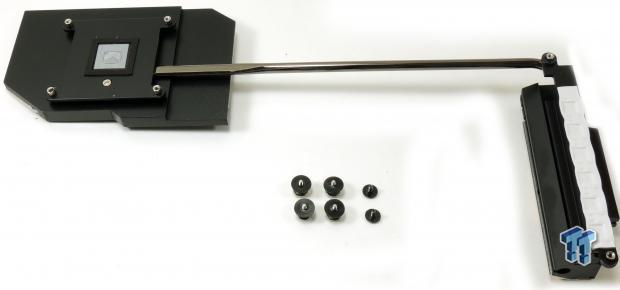
The heat sink is one solid piece. The heat sink uses screws and makes good contact with components.
X99-SLI Circuit Analysis
Circuit Analysis
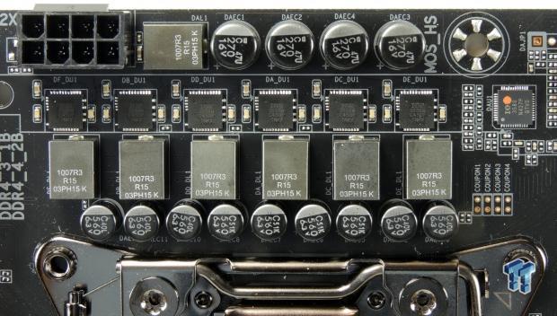
The CPU VRM features a total of 6 phases; each is powered by an integrated power stage, the well-known International Rectifier (Infineon) PowIRstages. There are six high capacity server grade inductors made by Cooper Bussmann. The FP1007R3-R15-R are 0.15uH Flat-Pac series power inductors, they feature 76A saturation current at 25C, this is an extremely high current rating, and will help reduce overall heat around the VRM area. The X99-SLI uses 9x Nippon Chemicon 10K can-type polymer capacitors each rated at 560uF for a total of 5040uF.
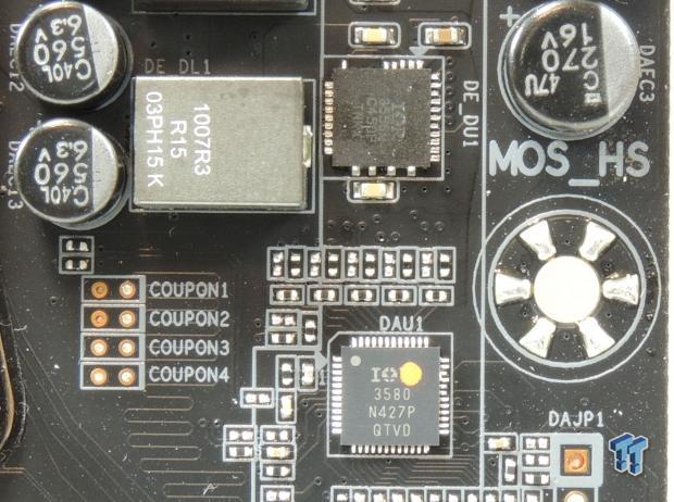
The X99-SLI is using the International Rectifier IR3580, an 8 phase digital PWM, the latest one that is offered by International Rectifier. GIGABYTE has used the IR3556 for the power stages; each one can output 50A at about 10W and 90% efficiency. The IR3556 is a brand new PowIRstage, it replaces the IR3551.
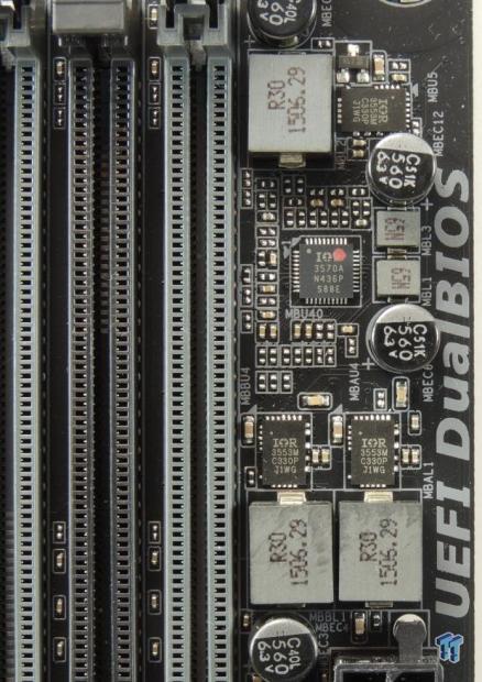
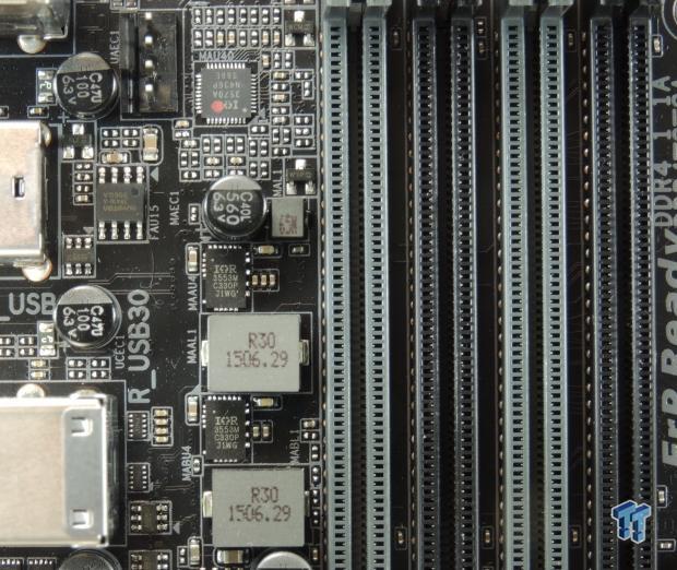
There are two sets of everything for the DDR4 power on X99, this is because there are two sets of DIMMs on every X99 motherboard. GIGABYTE chose to stay with digital PWM control for all four DDR4 VRMs; the International Rectifier IR3570 is a 3+2 phase digital PWM perfect for this. Two of these PWMs are in use, one on each side of the board.
There are four DDR4 VRMs because each set of DIMMs requires a DRAM voltage of 1.2v and a DRAM VPP voltage of 2.5v. The 1.2v rail is the most important, and on this board each set of DIMMs get one phase, powered by a 40A International Rectifier IR3553. The VPP is powered by a single phase that also uses the IR3553.
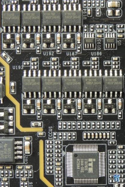
This array of 9x Richtek RT9018 is used to power individual pins in the socket. Since GIGABYTE and other manufacturers have added extra pins into the CPU socket they need to power those pins independently of the CPU, and thus linear regulators are used. An IT8792E is an embedded controller (one of 3 extra) which controls these linear regulators. This circuit design has some pleasing aesthetics.
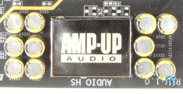
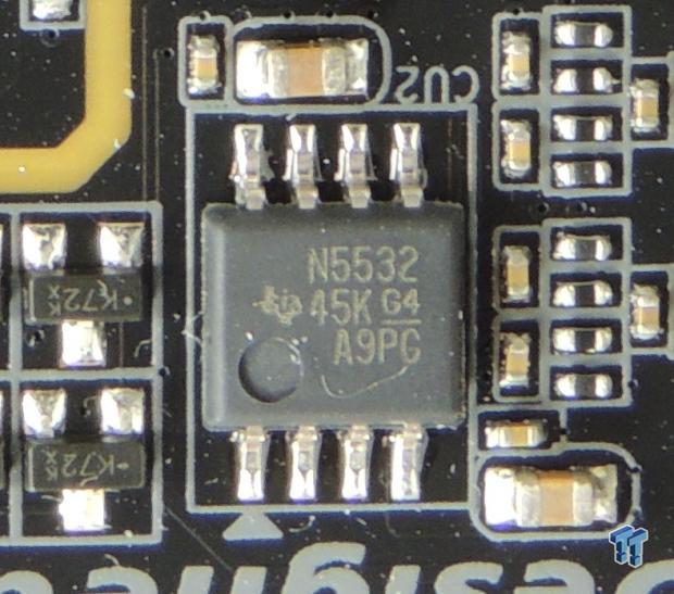
Under the EMI shield is an ALC1150 and a Texas Instruments NE5532 is used to amplify the output for the backpanel IO headphone jack.
X99-SLI Circuit Analysis Continued
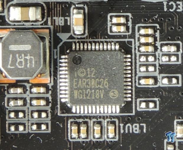
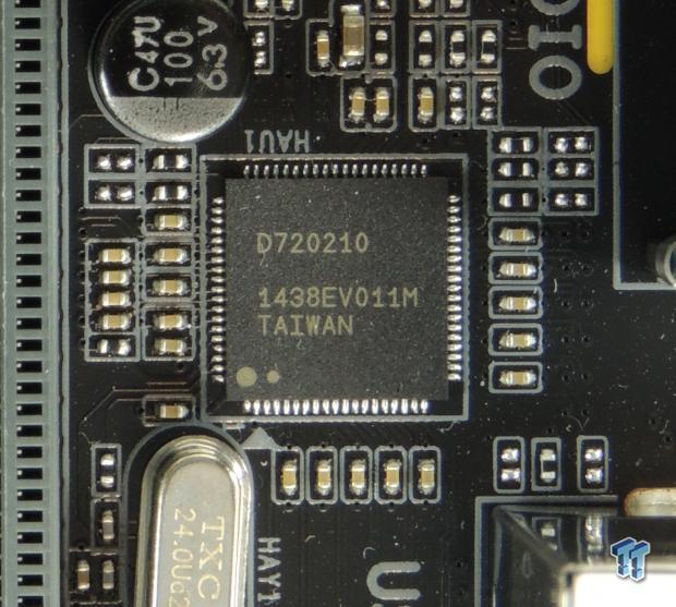
An Intel i218v is provided as the PHY for the integrated GBit NIC. Four of the USB 3.0 ports on the backpanel are routed through a NEC/Rensas D720210 which is a 1-to-4 USB 3.0 hub.
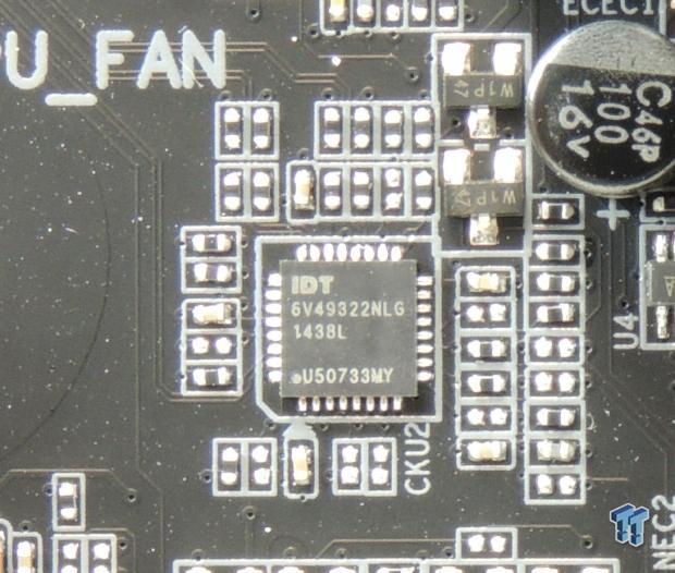
An IDT6V49332 is a clock generator which basically helps out with BCLK overclocking.
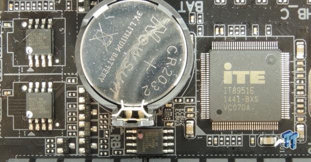
Dual 128Mbit (16MB) BIOS ROMs are provided along with an IT8951E which allows for the addition of USB BIOS recovery in case DualBIOS doesn't work.
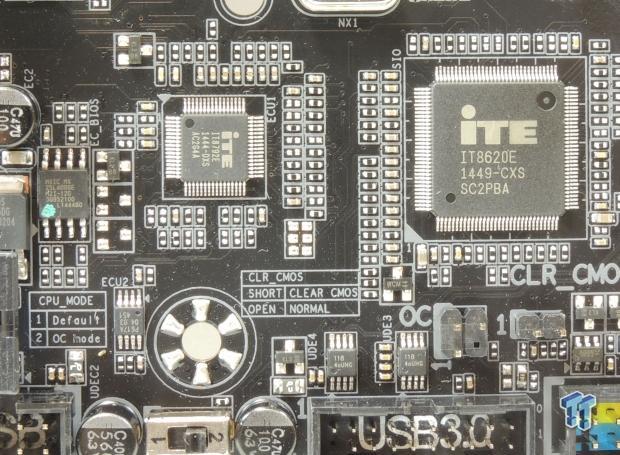
The main SuperIO is an IT8620E which monitors and controls voltage, temperature, and fans. It also provides the PS/2 keyboard and mouse ports on the back. A secondary EC is used, the IT8792E, and it helps the SuperIO. Four nuvoTon NCT3941S provide voltage mode fan control of four headers.
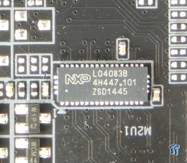
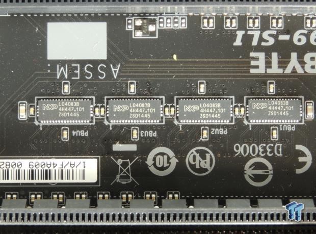
A single NXP L04083B switches bandwidth from the SATA Express (2 SATA ports) to the M.2 slot if needed. Four other NXP L04083B switch two PCI-E lanes each from the first PCI-E 16x slot to the second.
BIOS and Software
BIOS
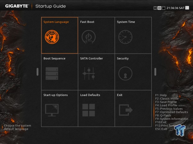
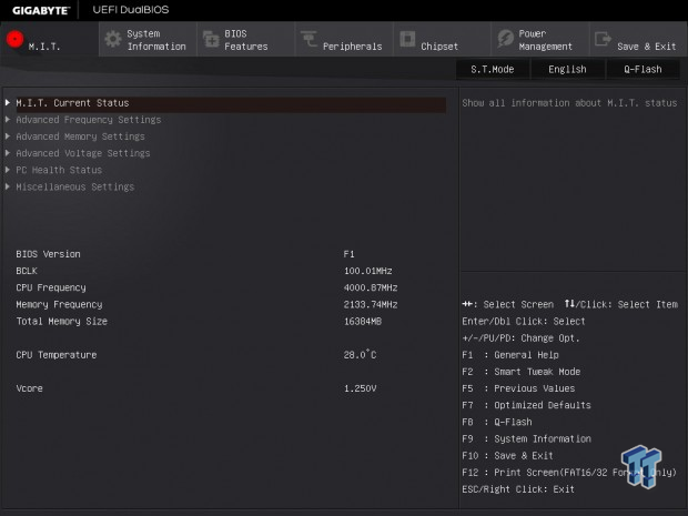
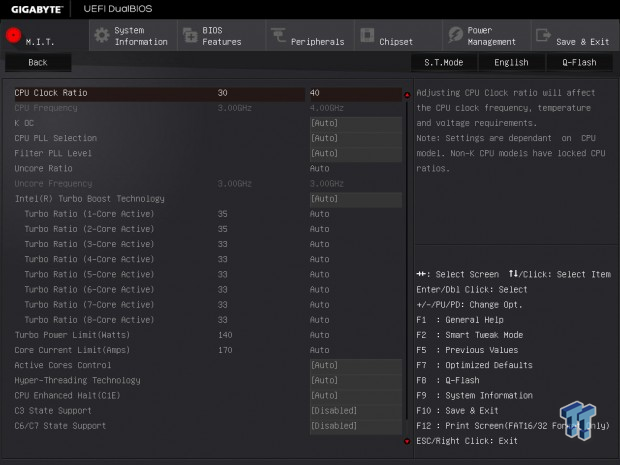
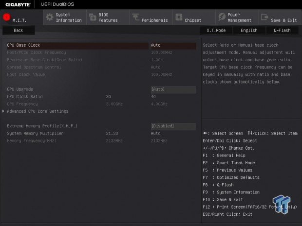
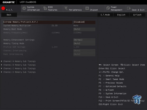
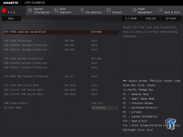
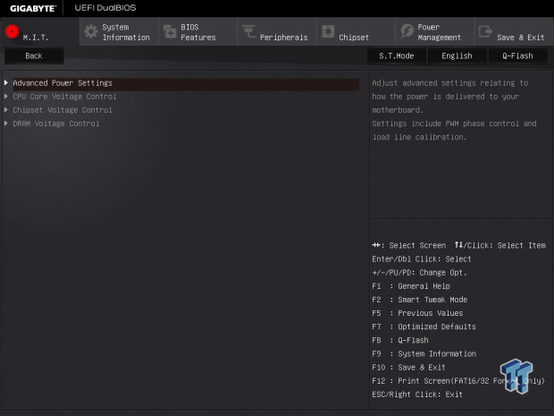
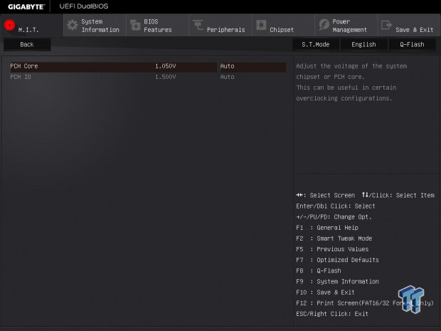
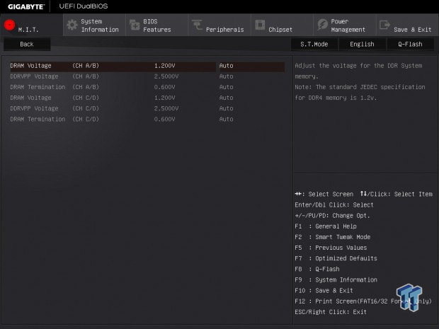
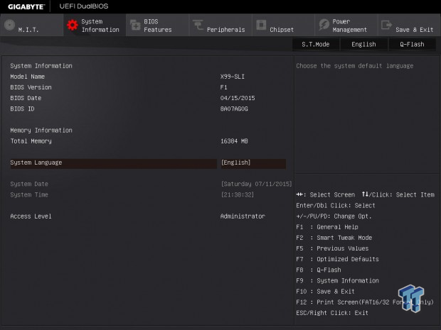
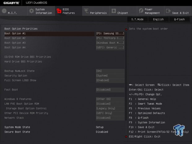
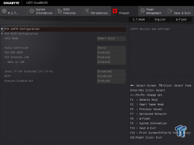
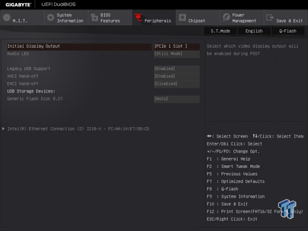
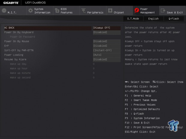
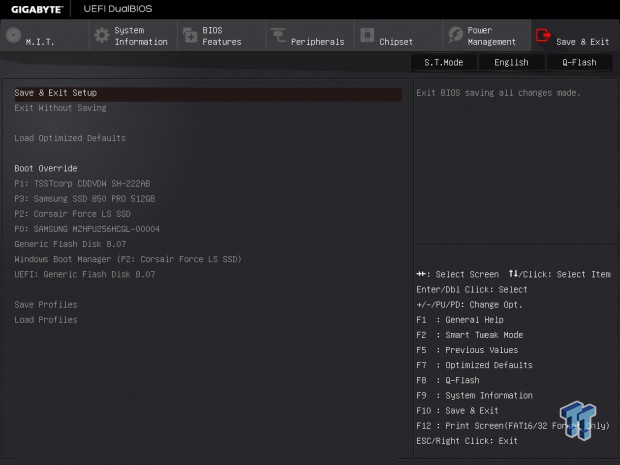
With these X99 GIGABYTE boards, you should really only use the classic mode (gray BIOS) by pressing F2 when you are greeted by the very basic mode upon entrance into the UEFI. From the classic mode, you can access all the settings, including overclocking. While I only have access to the F1 BIOS, the first release for the X99-SLI, everything worked very well.
Bugs from first wave GIGABYTE X99 motherboards, such as the rebooting that occurred with certain USB drives plugged in have been solved, and the UEFI performs better than one would expect from a $250 product (as long as you use classic mode BIOS).
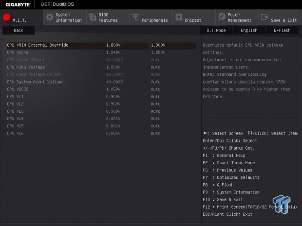
Overall, I was impressed by the maturity of this first release UEFI. I do, however, wish that GIGABYTE would expand fan control, perhaps provide a GUI. When you enable the CPU mode switch, 6 extra voltages become available under the CPU voltage menu.
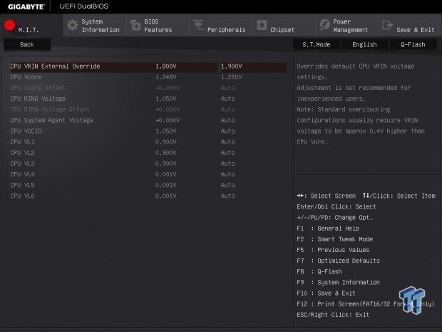
Only VL4, 5, and 6 should be increased. First start off with 1.44 or 1.45v on VL6 for cache overclocking. VLs will increase by auto rules, so you might not have to change them at all.
Software
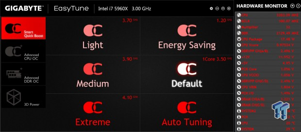
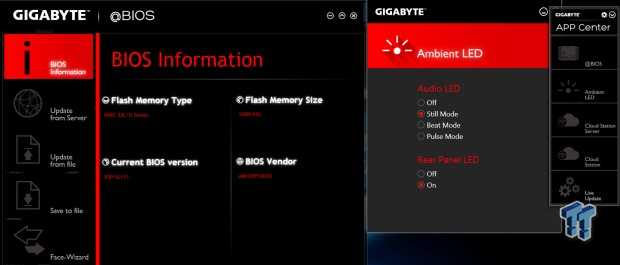
EasyTune is the go to program for most novice overclockers and it presents a decent amount of tuning options and monitoring. GIGABYTE also provides other programs through the APP center such as @BIOS, Ambient LED, Cloud Station, Smart Recovery 2, Fast Boot, Smart TimeLock, and SIV.
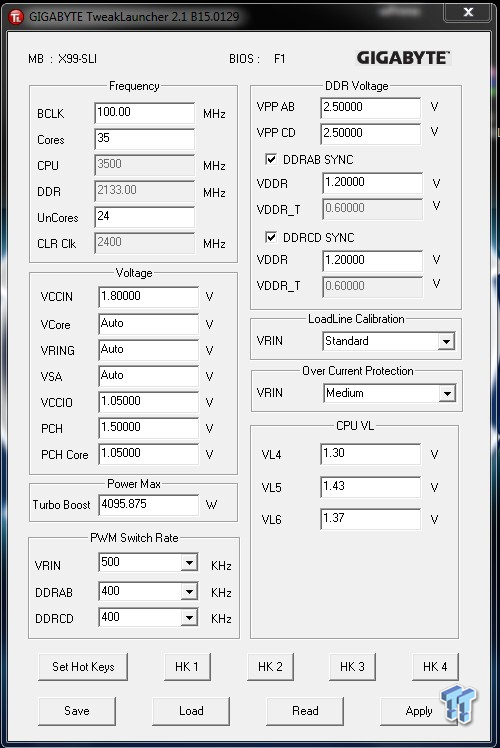
For more advanced overclockers, GIGABYTE Tweak Launcher (GTL) is much simpler and better.
Test System Setup
Test Setup
A big thanks to Corsair for sponsoring the case, fans, SSD, USB drive, and PSU! A big thanks to Seek for sponsoring the Thermal Camera. You can find my review of the camera here.
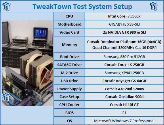
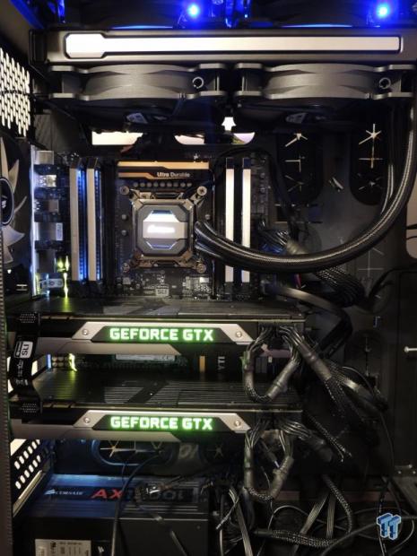
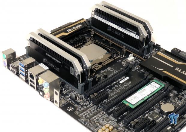
This is the new test bench, and it is designed to test every aspect of the motherboard and IO. I have designed it so that the motherboard sits in a case and is cooled by fans always on at a constant rate to keep the conditions similar for all tests. I have cut out part of the case behind the motherboard so I can get thermal images of the back of the PCB where the VRM heat spreads. System and CPU power measurements are now digitally logged.
I am also using a Netgear Nighthawk X4 AC2350 for our network (including wireless AC) tests. The latest M.2, SSD, and USB technologies are also being utilized to test the maximum potential of the motherboards that are being tested.
Overclocking
Overclocking Results
In this section, I will go through overclocking this board.
CPU Overclocking
Max CPU Overclock is found by setting the VCore to 1.5v, Input voltage to 2.1v, cache voltage to 1.15v, booting with a CPU multiplier of 45x and disabling any features that would result in CPU frequency fluctuation. I then proceed into Windows and use software to increase the multiplier; in this case I opted to use GTL.
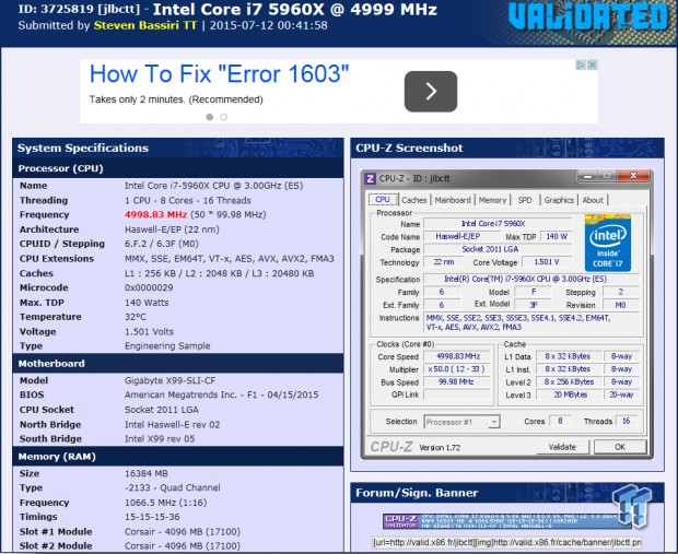
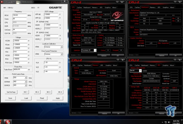
5.0GHz is the maximum of our CPU on this board and other X99 motherboards. It is clear that CPU overclocking is pretty good for high frequency. Maximum AIDA64 Stable Overclock (BIOS settings below for this):
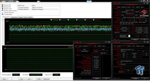
I was easily able to pull off 4.5GHz on the CPU with 3.2GHz cache and a 2133MHz overclock on my memory manually tuning the UEFI.
Uncore/Cache Overclocking
Boards with the extra pins in the socket can overclock the cache further, on the X99-SLI I was able to OC the cache to 4.3GHz, while the core was 4.5GHz.
Memory Overclocking
This section is a new addition. Corsair was nice enough to provide a 3200MHz quad-channel DDR4 kit for our benchmarks, and I decided to see how easy it is to boot with their XMP profile on different motherboards. In the early days of X99 trying to boot with the 32x memory multiplier was a nightmare, some boards did it with a lot of training (loops on startup), and some didn't even have the option. At this point in time I decided to test out how easy it is to use on each board.
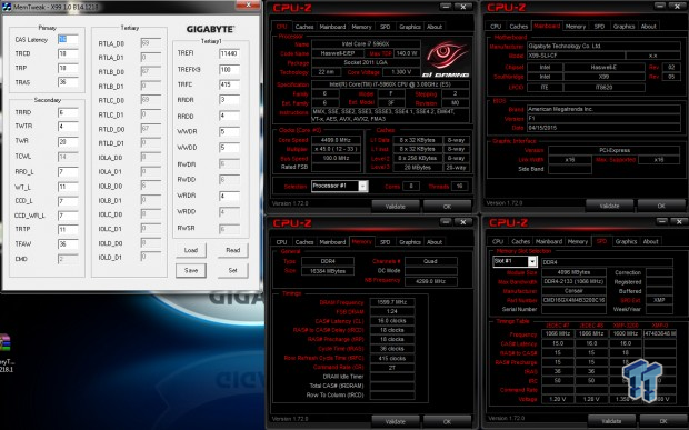
The X99-SLI handed this kit with ease and when I loaded XMP it set the 32x multiplier from the get-go. I was able to boot into Windows and there was no noticeable memory training upon the first boot. I then restarted from Windows and had no issue with memory training again. I then shut the computer down, waited 5 minutes and powered up, the board performed perfectly.
CPU, Memory, and System Benchmarks
CINEBENCH 11.5
wPrime
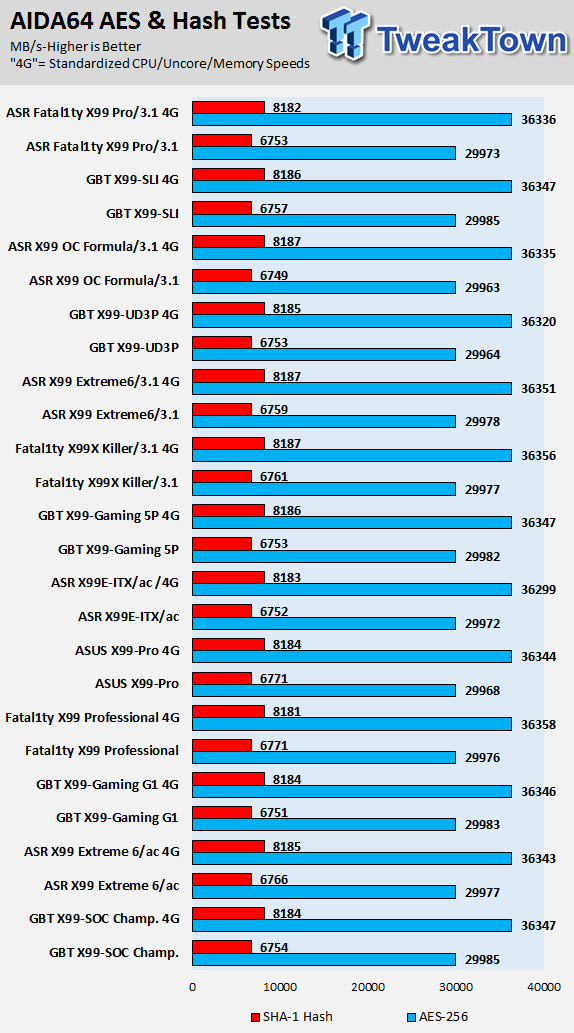
AIDA64 AES and HASH
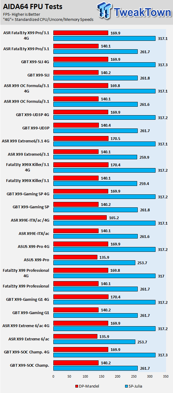
AIDA64 FPU
AIDA64 Memory

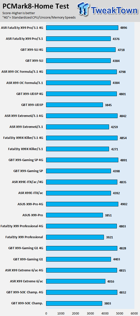
PCMark8 Home Test
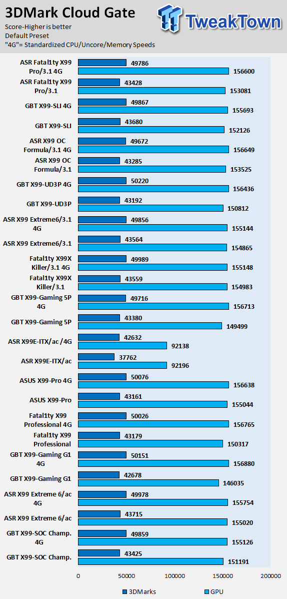
3DMark: Cloud Gate
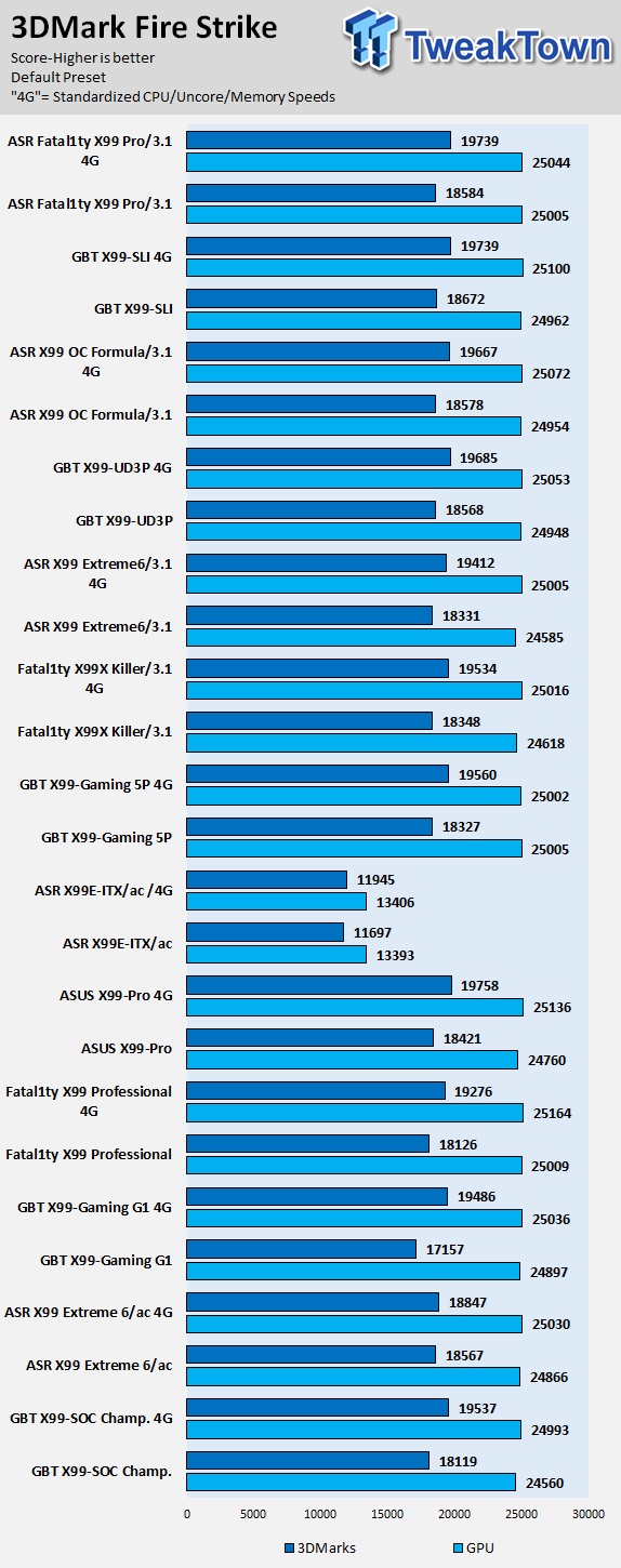
3DMark: Fire Strike
Resident Evil 6
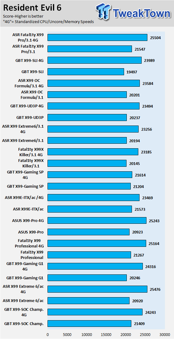
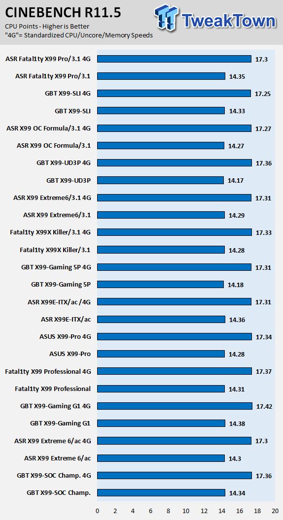
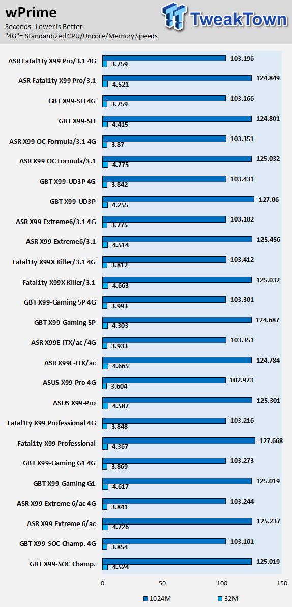
CPU, memory, system, and 3D performance are all very strong and there don't seem to be any issues.
These benchmarks are to find either exceptional performance or flaws, however, in this case, the X99-SLI is a solid motherboard with some nice surprises. Overall performance was very good, especially in 2S benchmarks. Also there aren't many third-party ICs on the board, it's a very basic board, and that usually leads to very good pure performance.
System IO Benchmarks
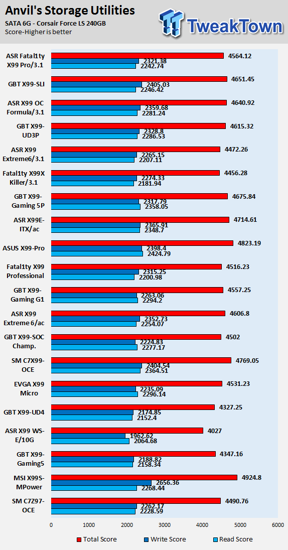
Anvil SATA6G:
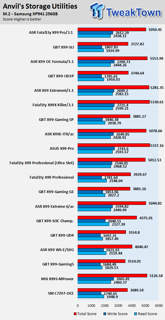
Anvil M.2:
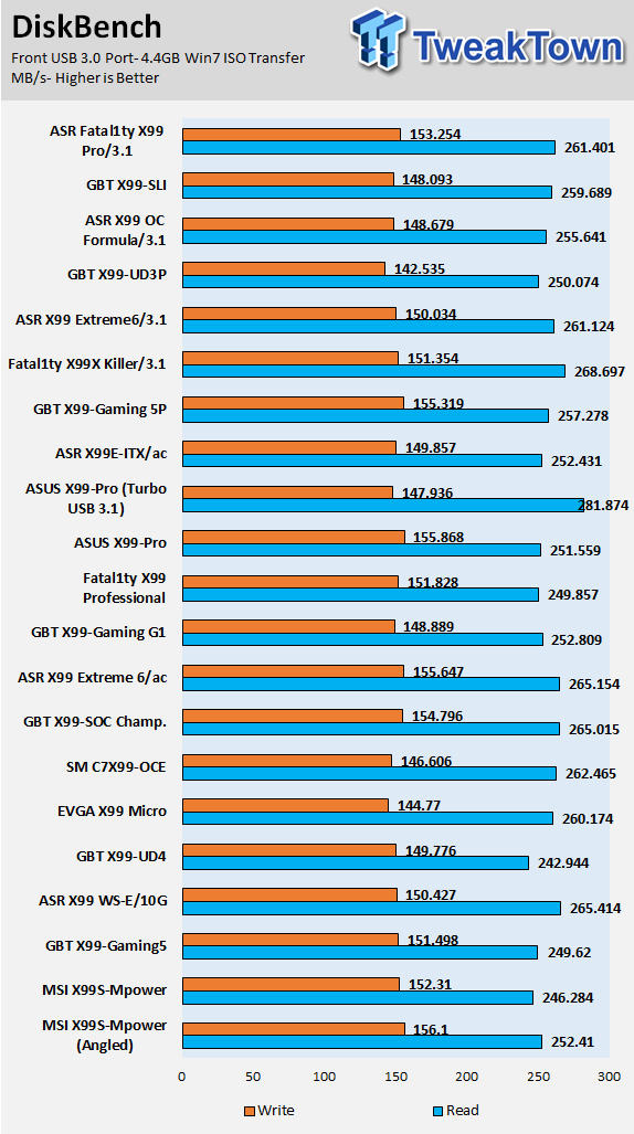
DiskBench USB 3.0:
ixChariot Network Throughput:
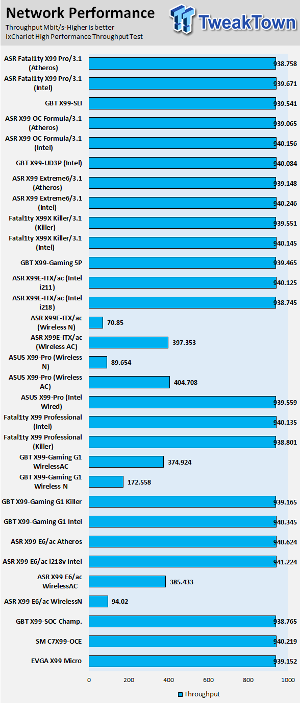
IO performance is where I expected it to be, it's towards the strong side of IO performance. SATA6G storage performance is solid. M.2 performance isn't the best because this is a M.2 PCI-E 4x drive in a M.2 2x slot.
Audio RMAA 5.5:
I disable all audio features, set the correct bitrates, and then test the audio with a loopback test.
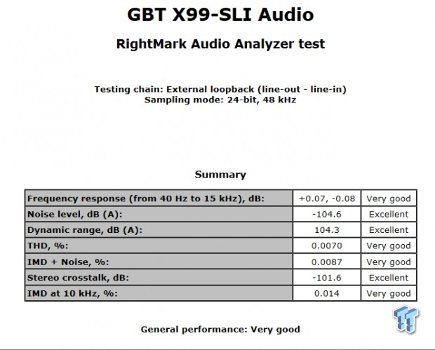
Sound Judgment by Ear: 4. Very Good, clear audio with slight boost from the on-board amplifier. There are 5 ratings for audio: 1. Problems, 2. Okay, 3. Acceptable, 4. Very good, 5. Excellent
Thermal Imaging and Power Consumption
System power usage is measured at the AC/DC PSU (the Corsair AX1200i) which I have connected to another system to measure the test system and as a backup I have a wall meter to verify. The CPU power is measured through the 8-pin connector which is hooked up to a hall effect IC which measures current and puts out a voltage in proportion to the current. That voltage is logged by a National Instruments ADC which logs the DC voltage level, which I then convert into current.

Note on Thermal Images: In the temperature section, we use our Seek thermal imaging camera to capture the surface temperatures of major components on the board; I look at the VRM and then all other things that light up the screen. If there is something to worry about then I will state it, otherwise I will just show the hotter running parts of the board for fun. Unless some component is over 80-90C then there really isn't anything to worry about.
All systems will act differently, so I will look for commonalities, such as how far from the VRM the heat spreads through the PCB and the difference in temperature between the front side and backside of the PCB. Keep in mind that the majority of the heat from the VRM goes into the PCB as it is a giant soldered on copper heat sink. A larger difference in temperature between the back and front of the PCB points towards a more effective heat sink.
Thermal Testing at Stock Speeds:
The image on the left is always at idle and the image on the right is at load.


Full frontal.
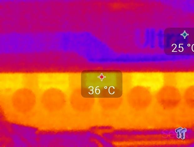

Up-close of the front of the VRM.
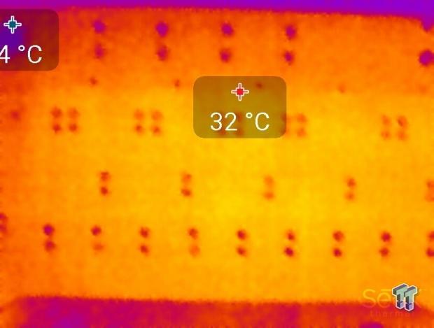
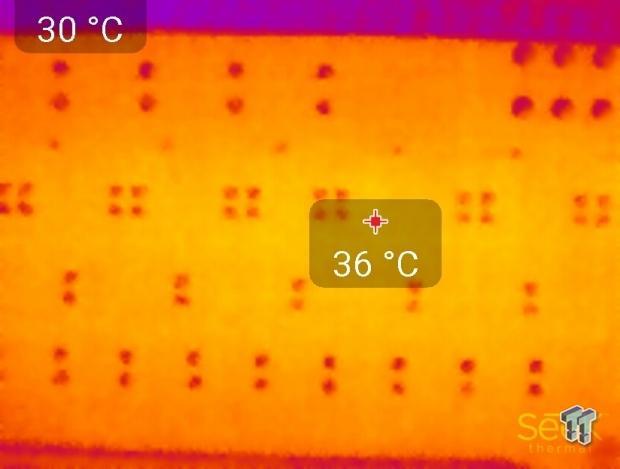
Up-close of the back of the VRM.
Thermal Testing at 4.5GHz Overclocked Speeds:


Full frontal.

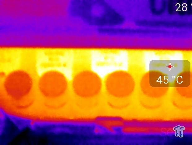
Up-close of the front of the VRM.
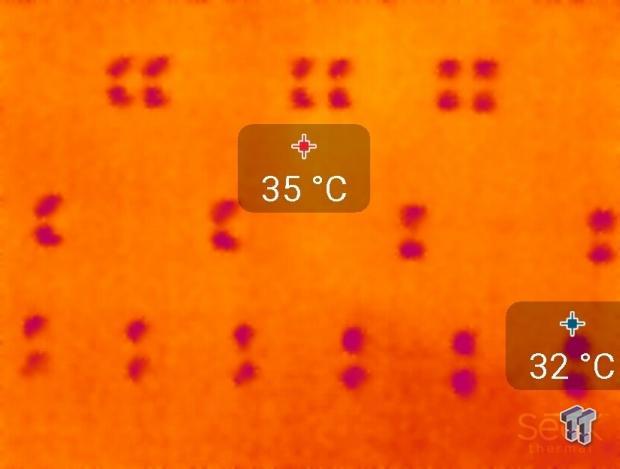

Up-close of the back of the VRM.
The VRM components on this motherboard are the same ones GIGABYTE uses on its top of the line overclocking motherboards. Temperatures on the backside never exceeded the temperatures on the front of the motherboard, indicating solid heat sink performance. Even though this is a 6-phase VRM, it performs as well as some 8 and 12 phase VRMs I have seen on other boards.
Board makers can either use high power density or more phases to achieve an overclocking capable X99 motherboard, GIGABYTE has definitely focused on power density. Don't let the fact that the board only has 6 phases faze you (no pun intended); it's enough for any air or water overclock. Anything under 60C is excellent, 60-80C is acceptable, and anything above 80C is a bit worrisome (if at stock).
What's Hot, What's Not & Final Thoughts
This is where you can fast forward to the final section of the review, and get a quick recap and points on the GIGABYTE X99-SLI.
What's Hot
Solid Quality and Overclocking: GIGABYTE's attention to detail when it comes to quality is quite apparent. For example, the VRM is only a 6-phase VRM, but because of its high quality components, it's able to overclock the CPU core frequency as high as every other X99 motherboard I have tested.
LGA2011-V3 with 2089 pins: With the second round of X99 motherboards, most manufacturers now have extra pins in the CPU socket. These extra pins provide higher cache overclocking and better support for high speed DDR4 overclocking. The X99-SLI provides those extra pins and the hardware to go with it.
Solid Performance: The board performed very well compared to the rest of the herd. I didn't find any scores that were unusual or pointed towards a problem with bus bandwidth or tuning.
Great Power and Thermal Performance: Since GIGABYTE isn't using many third-party ICs, overall power consumption is pretty low. The high quality VRM components also help with reducing temperatures around the VRM area, and this is apparent through the thermal imaging.
Fair Price: I personally feel that for $250, you should get all the platform features and a some unique manufacturer features. On this front, GIGABYTE delivers with good value, all the features of the X99 chipset, and some new GIGABYTE features.
What's Not
No POST Code display: The lack of power, reset, and clear CMOS buttons isn't such a big deal since users can just hook up buttons to the motherboard jumpers, but one thing users cannot easily do is implement a POST Code display. I think that on a $250 motherboard there should be some type of POST code display to be used not only for overclocking, but overall diagnostics.
Standard M.2 slot: While something built to its standard isn't necessarily a bad thing, GIGABYTE could have gone above the M.2 standard like they did on their X99-SOC Force. The M.2 form factor has become increasingly popular because of its ability to provide huge bandwidth gains over SATA 6G and even SATA Express, and M.2 drives that can saturate the standard 2x PCI-E 2.0 M.2 slot are becoming more popular and affordable.
Final Thoughts
This is an interesting board because of where it sits within the GIGABYTE X99 fleet. It's peculiar that GIGABYTE's X99-UD4P is only $20 more, as it only offers some extra LEDs and a different form factor. Looking closer, it becomes apparent that there are other differences, and the X99-SLI is designed for a slightly different case layout than the X99-UD4P.
For starters, GIGABYTE moved two of the USB 3.0 ports on the IO panel to an extra internal USB 3.0 header leaving only four USB 3.0 ports on the back panel, and they moved most of the fan headers from the right side of the board towards the left. It seems to me that GIGABYTE is trying to target everyone with their X99 fleet, and the X99-SLI is the birth child of consumer demand.
The X99-SLI is priced aggressively at around $250; it's a solid X99 motherboard that won't break the bank. The X99-SLI offers great overclocking and it's quite easy to use with the Corsair DDR4 3200MHz kit, even for 24/7 use. Overall, I was pleased with the X99-SLI, and while it might not have the most USB 3.0 ports or the fastest M.2 slot, it does offer good compatibility and performance because most if not all of its controllers are from Intel. GIGABYTE has done a nice job of providing a great variety of products for the X99 market, and if you are looking for a board in the $250 price range, you should give the X99-SLI a look.

