The Bottom Line
Introduction, Specifications, and Pricing
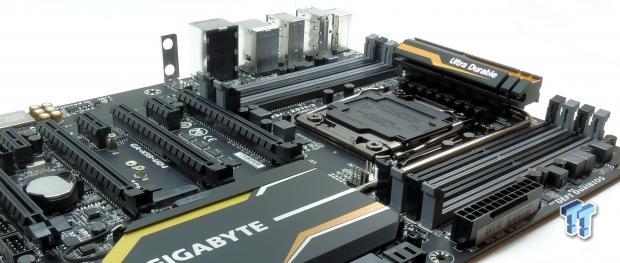
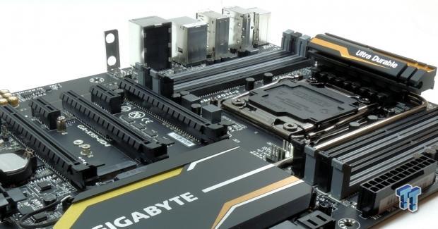
GIGABYTE is a well-known manufacturer of computer hardware, and today I will give you a look at their X99-UD4. The X99-UD4 falls into GIGABYTE's Ultra Durable category for motherboards. It isn't specifically aimed at overclockers or gamers, but rather anyone looking for a versatile board with quality components.
The X99-UD4 doesn't carry specialized features, instead it provides all the Intel chipset features with some upgrades in the audio section. While it might not be labeled a gaming or overclocking motherboard, it still should hold its own when it comes to both.
So, let's take it for a spin.
Specifications
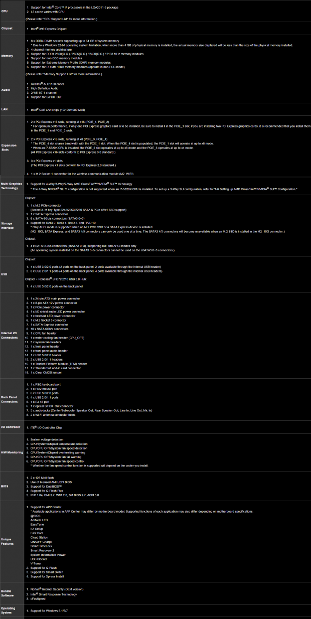
The X99-UD4 supports a number of the latest X99 chipset features such as 8 DIMMs with 64GB of memory support, M.2, 10x SATA 6G ports, and SATA Express.
Pricing
At $255 on Newegg, the X99-UD4 is at the midpoint for X99 motherboards.
PRICING: You can find the GIGABYTE X99-UD4 (Intel X99) Motherboard for sale below. The prices listed are valid at the time of writing but can change at any time. Click the link to see the very latest pricing for the best deal.
United States: The GIGABYTE X99-UD4 (Intel X99) Motherboard retails for $249.99 at Amazon.
Canada: The GIGABYTE X99-UD4 (Intel X99) Motherboard retails for CDN$319.00 at Amazon Canada.
Packaging and the X99-UD4
Packaging and the Board
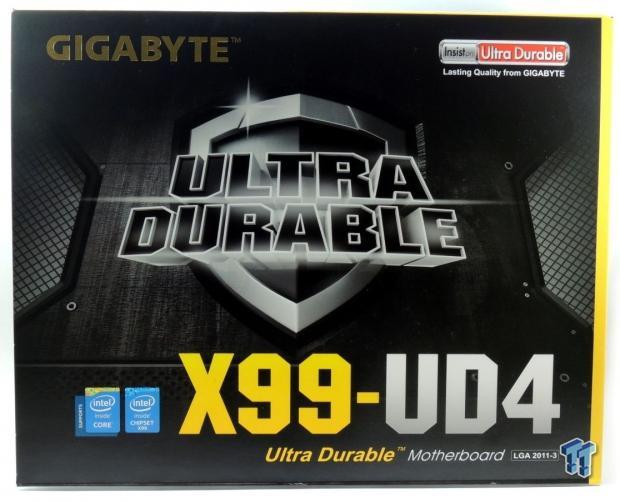
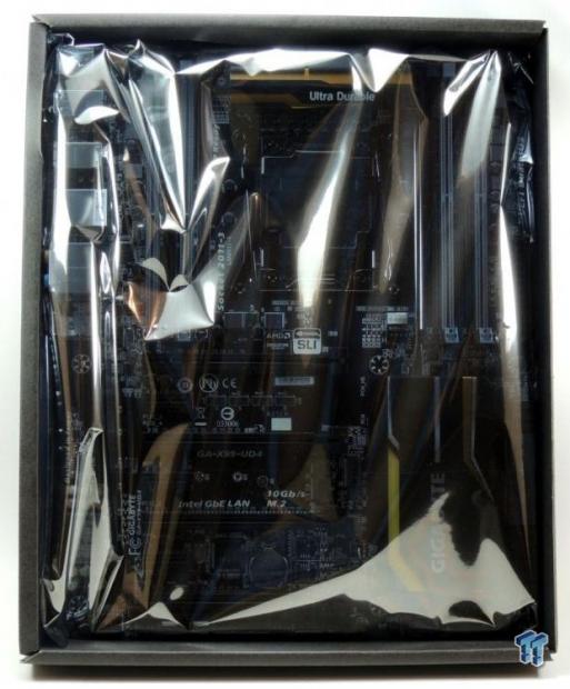
The box is what you would expect. The board sits inside an anti-static bag inside a small box. The board seems secure. This is the same type of packaging I saw with the X99-Gaming 5.
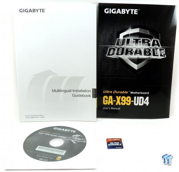
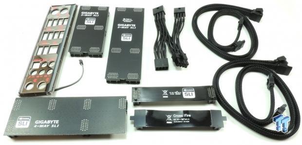
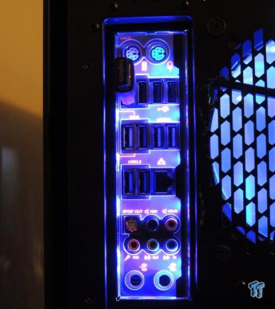
The accessory package provides almost everything you would need for an X99 build. It includes: driver DVD, manuals, case sticker, four braided SATA 6G cables, 8-pin CPU power expander, 2-way SLI and CrossFireX bridges, two 3-way bridges for different GPU spacing, a 4-way SLI bridge, and a IO shield that lights up. This is almost the same accessory package as the X99-Gaming 5, I am surprised (in a good way) that the light up IO shield is included as well as the two types of 3-way SLI bridges.
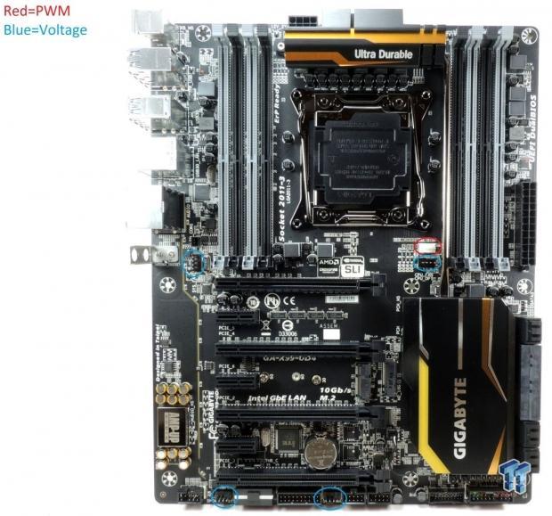
I have circled the fan headers on the board. There are a total of five 4-pin headers; I have highlighted in the image which headers support PWM and which support voltage mode. The board carries the same PCI-E layout as the other X99 GIGABYTE motherboards. I am not the biggest fan of gold, but the way it is done here with small gold accents is tasteful. The gray memory DIMMs are the ones you actually populate, so the black ports are the ones most people will see unless you fill up all eight DIMMs.
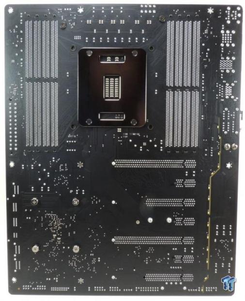
The gold accent on the PCH also lights up, along with the LEDs on the back of the board, which you can see in the test setup section of this review. The IO panel also lights up, but doesn't light up gold. The back of the PCB doesn't have any SMD components and the heat sinks are held down by metal screws.
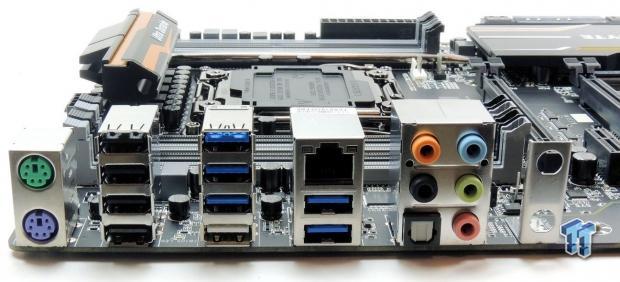
The back panel IO features an Intel NIC, six USB 3.0 ports (the white one is for USB BIOS flash back), four USB 2.0 ports, PS/2 keyboard and mouse ports, and a TOSLINK with S/PDIF optical. An additional supporting bracket for GIGABYTE's WIFI/BT M.2 module is also present.
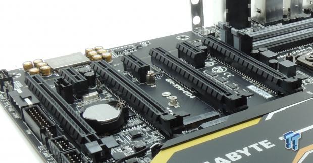
Four full sized PCI-E 16x slots bring a lot to the table in terms of PCI-E layout. If you use a 40-lane CPU then you can run 4-way SLI/CrossFireX at 16x/8x/8x/8x. The first and second PCI-E slots are hard wired to the CPU, the third PCI-E slot is a full 16x slot, however, 8x of that slot can be switched to the last PCI-E slot if the last slot is occupied. All the PCI-E 1x slots are hardwired to the PCH and don't share bandwidth.
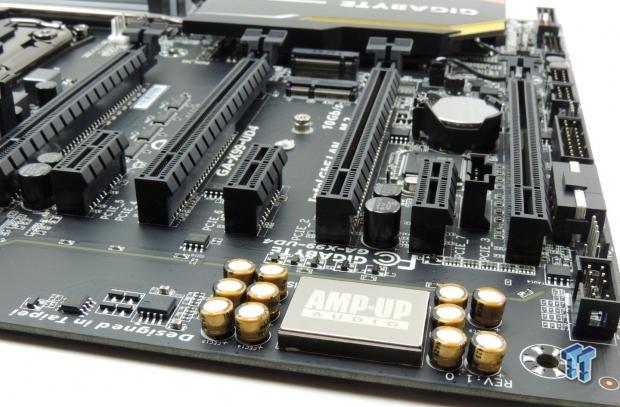
On the X99-UD4, GIGABYTE decided to upgrade their Realtek ALC1150 with some additional hardware I will cover later on. However, there is one additional amplifier for the backpanel IO headphone jack.

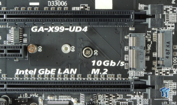
There are a total of 10 SATA 6G ports. The two ports in-line with the SATA Express connector will be disabled if the M.2 slot is used. So you can run those two SATA ports, M.2, or SATA Express.
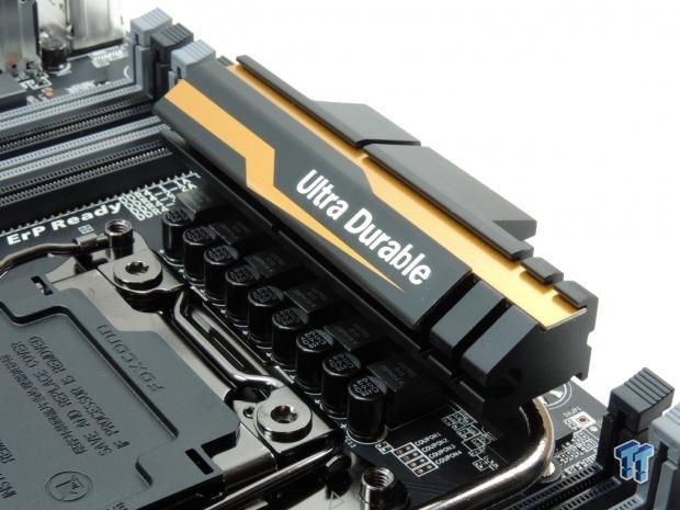
The X99-UD4 uses a 6-phase VRM. While that phase count might seem inadequate for X99, it actually isn't. This is because GIGABYTE is using high quality components and I will show you in the following sections that this isn't just any normal 6-phase VRM.
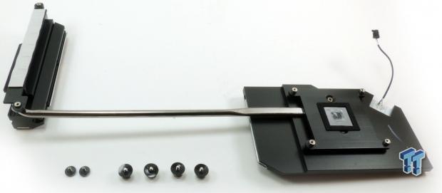
The heat sink is one solid piece. The VRM portion seems to make good contact with all the powerstages. A total of six metal screws hold down the heat sink.
X99-UD4 Circuit Analysis
Circuit Analysis
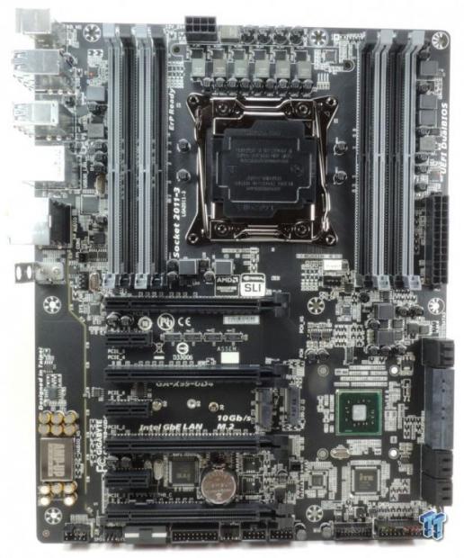
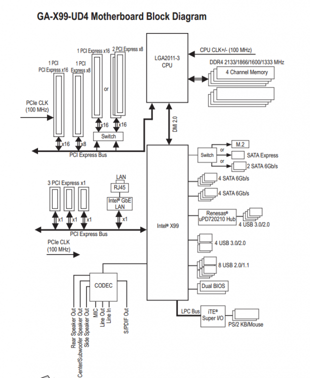
This section will start off with a look at power regulation and then shift into general circuit selection and implementation.
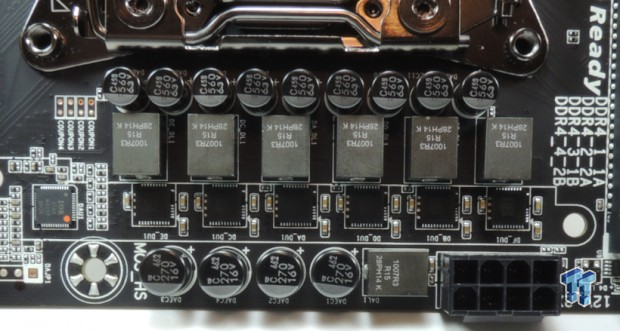
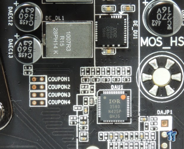
The VRM on this board is deceivingly powerful. It is powered by an IR3580 which is a popular PWM for overclockers. It is produced by International Rectifier who in recent years has been killing it with their high performance digital PWMs and power stages. Only 6 of the 8 phases are being utilized, however, GIGABYTE tossed in the IR3556 also produced by International Rectifier. Each IR3556 can provide up to 50A of current and the IR3356 is IR's second generation of integrated high-current power stages.
GIGABYTE chose to upgrade their inductors and is using 76A Cooper Bussmann high current inductors. The key to this 6-phase VRM's performance are the inductors. To tie things up, GIGABYTE is using nine of their Chemicon 10K black solid polymer capacitors for a total of 5040uF.
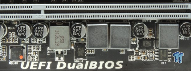
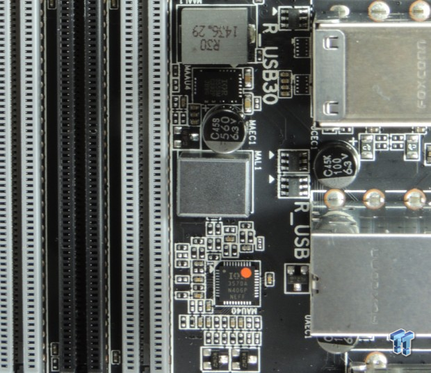
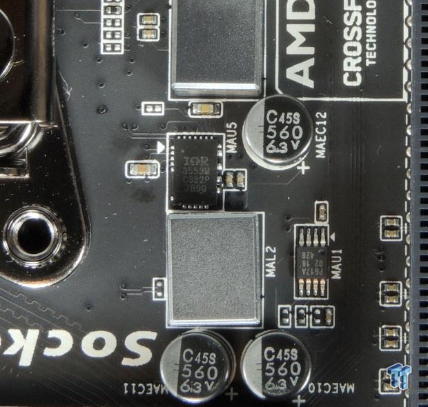
GIGABYTE decided to stick with International Rectifier for the memory VRs as well. For the main DDR4 and VPP outputs, the X99-UD4 is using IR3553's, which are 40A integrated power-stages from International Rectifier. Two IR3570 from International Rectifier are 3+2 phase digital PWMs, each controls the VRs for one set of four DIMMs.
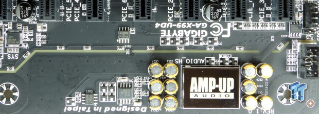
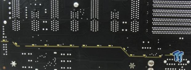
The X99-UD4 uses an ALC1150 for its audio codec which works in unison with the integrated Azalia audio processor in the PCH. The X99-UD4 has only one audio amplifier the Texas Instruments NE5532 which is quite common, it is used to amplify the backpanel IO's headphone jack. Nichicon audio capacitors are also present and GIGABYTE has isolated the analog audio lines from the digital domain of the rest of the motherboard. There are also 14 yellow LEDs on the back of the PCB, which illuminate the PCB divide.
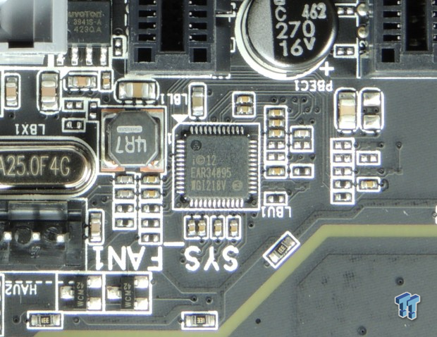
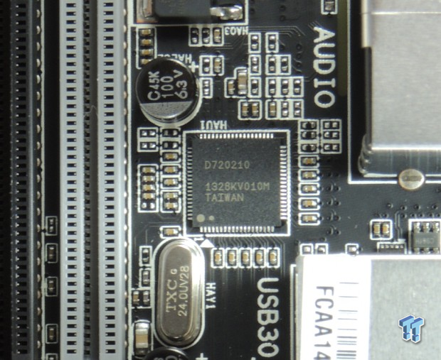
An Intel i218v is being used as the integrated NIC's PHY which many prefer because of Intel's strong reputation in the NIC industry. A Renesas D720210 is used to expand one USB 3.0 port into four ports for the backpanel IO.
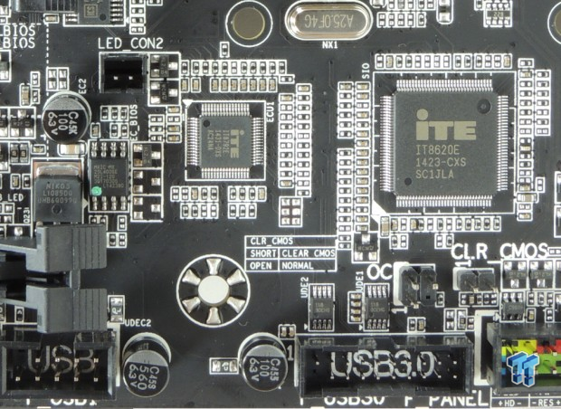
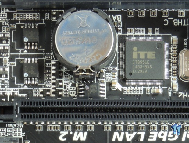
On the left are two iTE chips, the IT8620E is the Super I/O in charge of voltage, temperature, and fan monitoring and control. The IT9792E is an embedded controller (EC) which handles features such as overclocking, extra fan controls, or even LEDs. On the right are the two 128Mbit BIOS ROMs for Dual BIOS and an IT8951E which is used to power GIGABYTE's additional USB BIOS recovery. The additional recovery method can update the BIOS even if the system doesn't have a CPU.
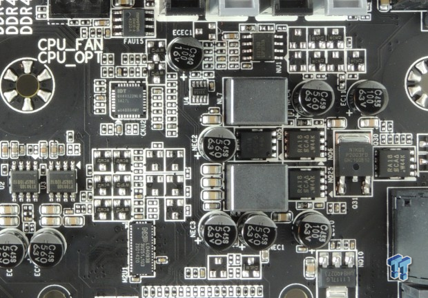
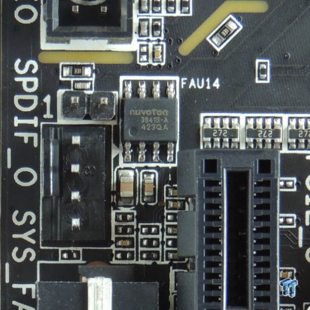
On the left is the PCH VRM powered by a single phase Richtek PWM and some Vishay MOSFETs. An IDT 6V49322NLG is an external clock generator which is supposed to help with BCLK overclocking. The NXP L04083B is a PCI-E quick switch used to switch between SATA Express and M.2. On the right is a nuvoTon NCT3941 which is one of four on the motherboard. They are used to control each voltage mode fan header, which require more motherboard hardware than PWM control, because voltage mode requires each header to have its own voltage regulator.
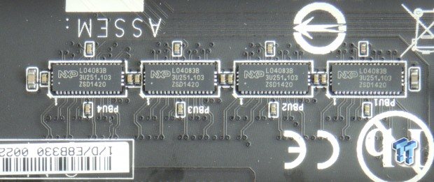
These four NXP L04083B switch 8X PCI-E 3.0 from the third PCI-E slot to the fourth.
BIOS and Software
BIOS
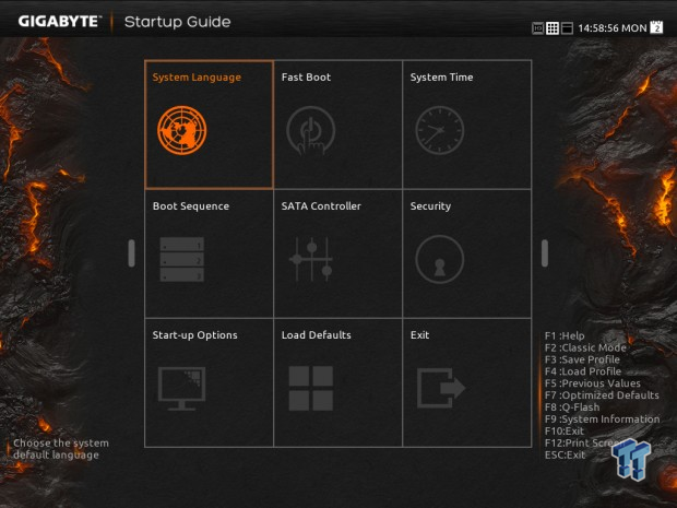
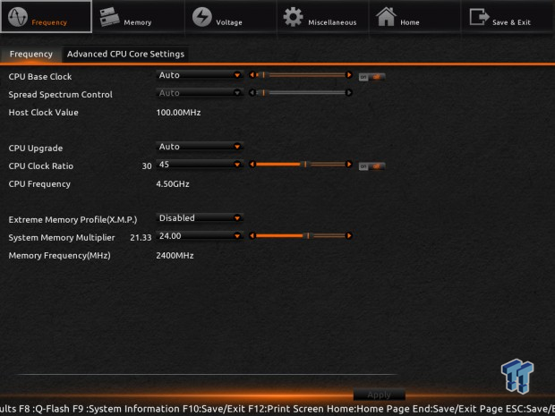
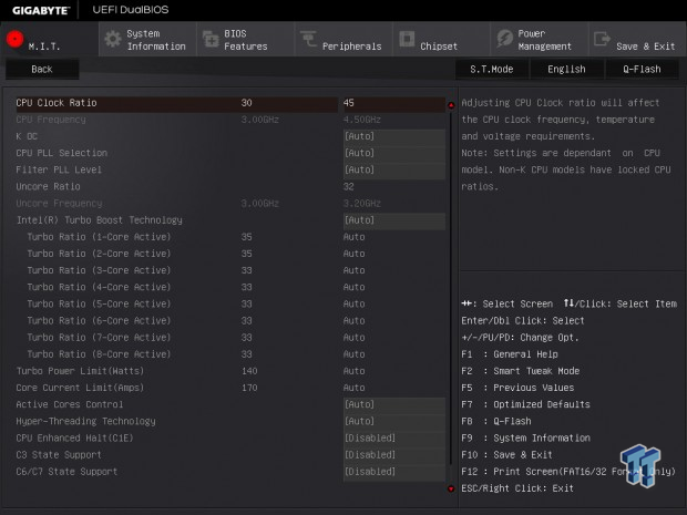
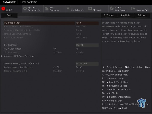
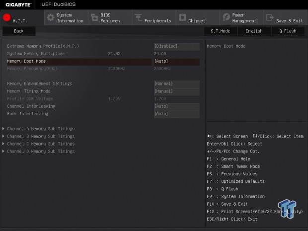
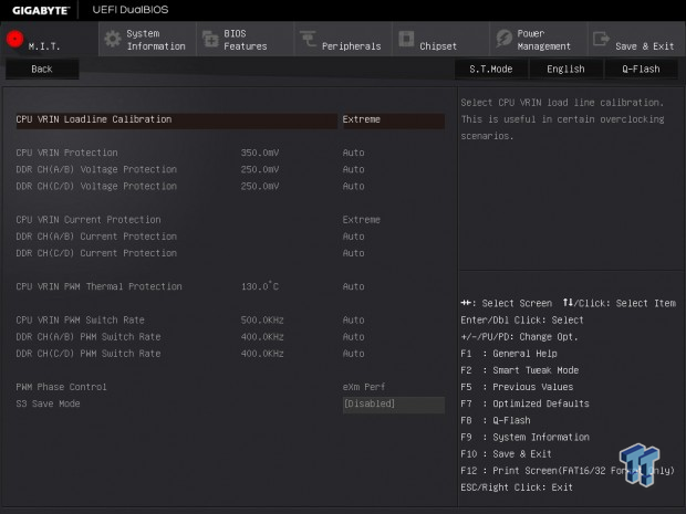
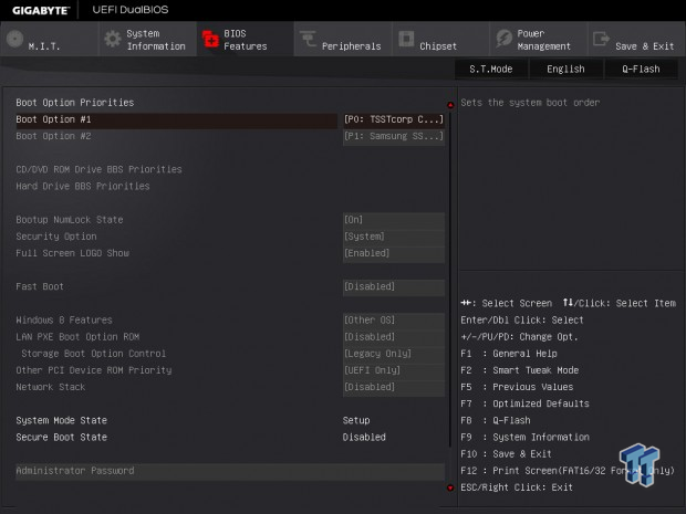
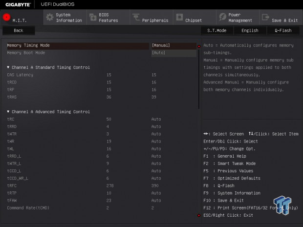
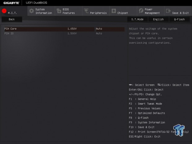
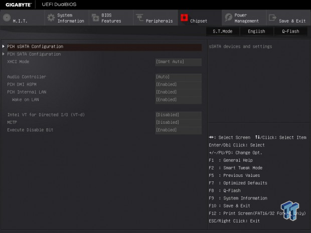
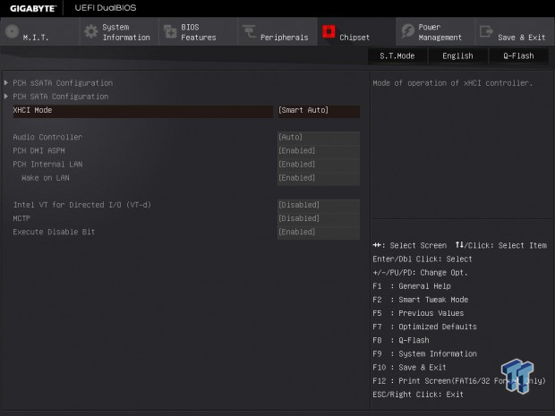
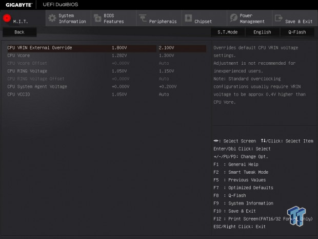
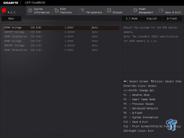
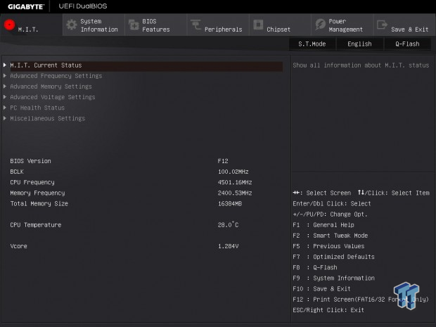
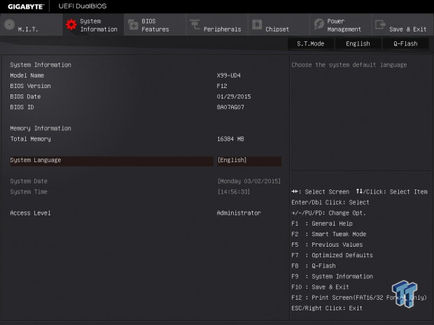
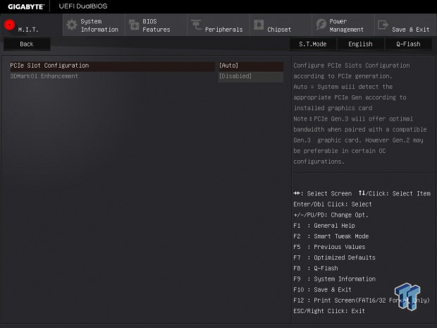
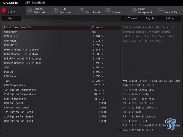
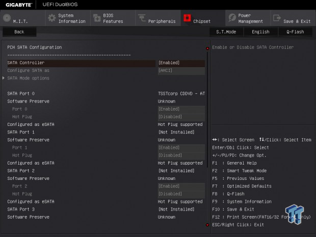
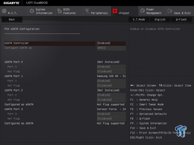
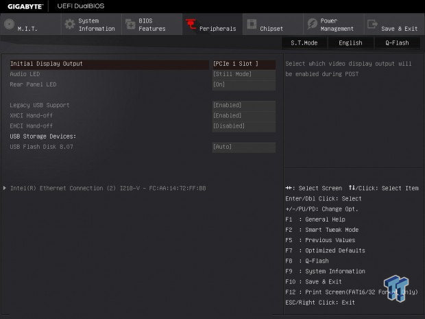
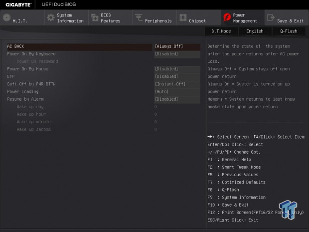
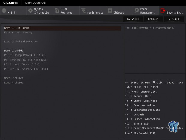
The BIOS on the X99-UD4, like the other GBT X99 motherboards, features three different operating modes. The first is an easy to use GUI that presents tiles, however, the second is an overclocking only menu in orange and black to compliment the first one. The third mode is the one to use, it is gray and black and has all the features together. When you boot up and are in the UEFI, press F2 to change between the BIOS modes.
All together, the BIOS was pretty stable and the settings work like they should, and overclocking was simple as well. There was a small issue with the board refusing to boot when certain USB thumb drives were plugged in during boot, but most USB sticks I tried didn't cause this issue.
Software
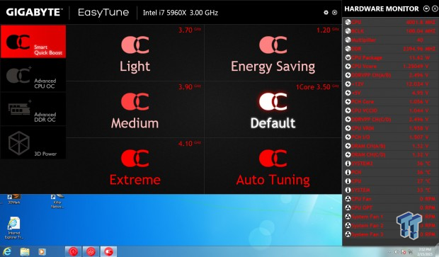
The X99-UD4 comes with the full software package which all GIGABYTE X99 motherboards feature. This includes EasyTune and System Information Viewer as shown above. These are the go to for those who want a nice GUI and guidance with overclocking.
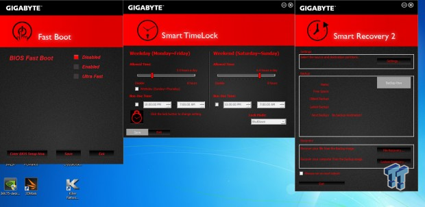
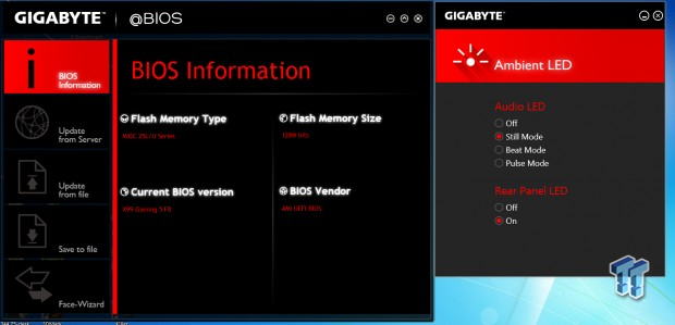
GIGABYTE also provides Fast Boot, Smart TimeLock, Smart Recovery 2, Ambient LED, and @BIOS with the X99-UD4. The Ambient LED program is neat, in that you can control the LEDs on the board, and even have them pulse to music.
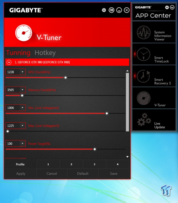
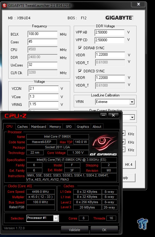
The X99-UD4 has V-Tuner which can overclock your GPU and the APP center which contains all the applications and Live Update which can update drivers and application with one click. GIGABYTE Tweak Launcher also works on the X99-UD4 and will allow you to overclock the CPU and memory on-the-fly.
Test Setup and Overclocking
Test Setup
A big thanks to Corsair for sponsoring the case, fans, SSD, USB drive, and PSU!
A big thanks to Seekfor sponsoring the Thermal Camera. You can find my review of the camera here.
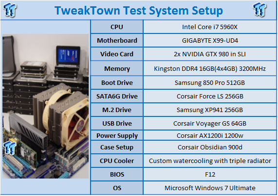
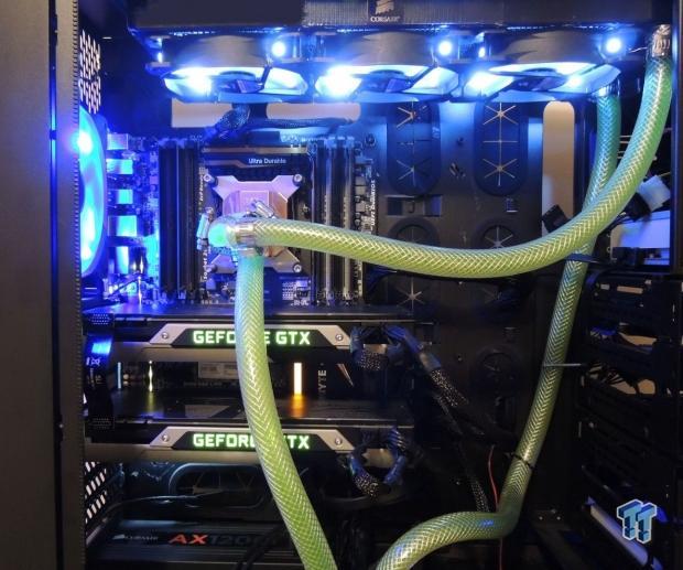
This is the new test bench, and it is designed to test every aspect of the motherboard and IO. I have designed it so that the motherboard sits in a case and is cooled by fans always on at a constant rate to keep the conditions similar for all tests. I have cut out part of the case behind the motherboard so I can get thermal images of the back of the PCB where the VRM heat spreads. System and CPU power measurements are now digitally logged.
We are also using a Netgear Nighthawk X4 AC2350 for our Wireless AC tests. The latest M.2, SSD, and USB technologies are also being utilized to test the maximum potential of the motherboards that are being tested.
Overclocking Results
In this section, I will go through overclocking this board.
CPU Overclocking
Max CPU Overclock is found by setting the VCore to 1.5v, Input voltage to 2.1v, cache voltage to 1.2v, CPU multiplier to 45x, memory and cache multipliers to 24x and 32x, and disable any features that would result in CPU frequency fluctuation. I then proceed into Windows and use software to increase the multiplier.
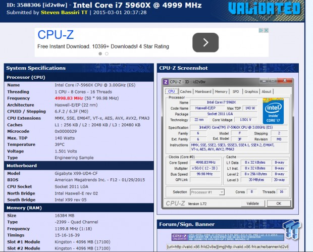
5.0GHz is the maximum of our CPU on this board and others.
Maximum AIDA64 Stable Overclock (BIOS settings below for this):
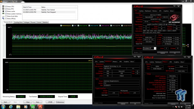
I was easily able to pull off 4.5GHz on the CPU with 3.2GHz cache and a 2400MHz overclock on my memory manually tuning the UEFI.
CPU, Memory, and System Benchmarks
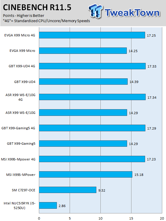
CINEBENCH 11.5
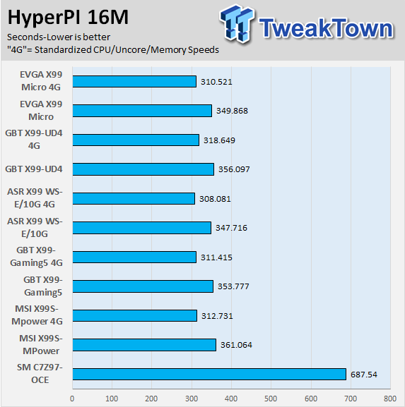
HyperPI
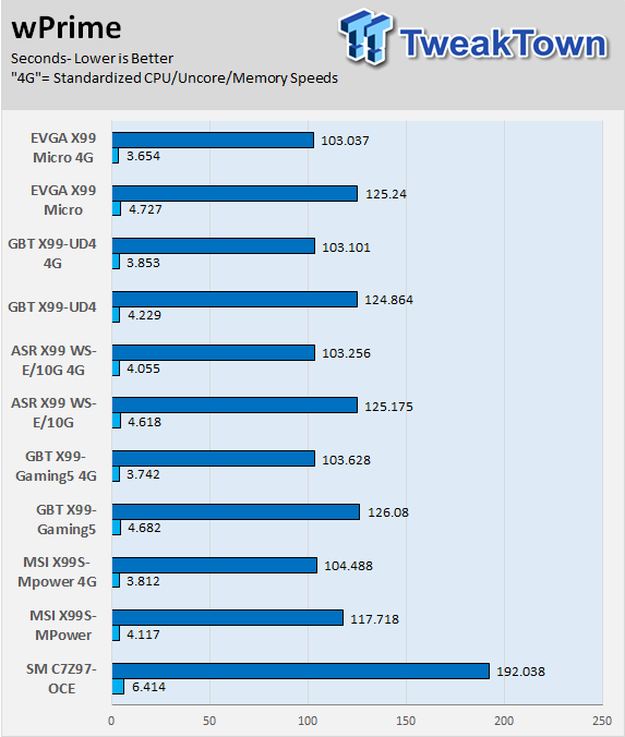
wPrime
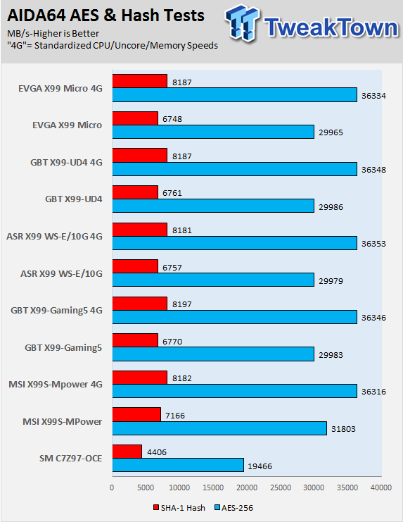
AIDA64 AES and HASH
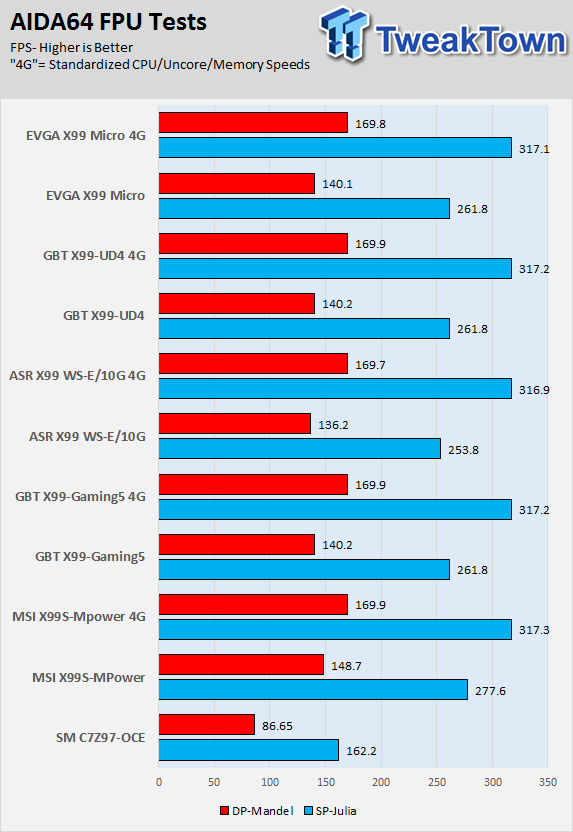
AIDA64 FPU
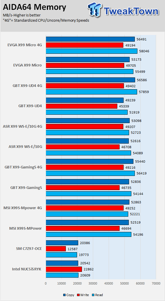
AIDA64 Memory
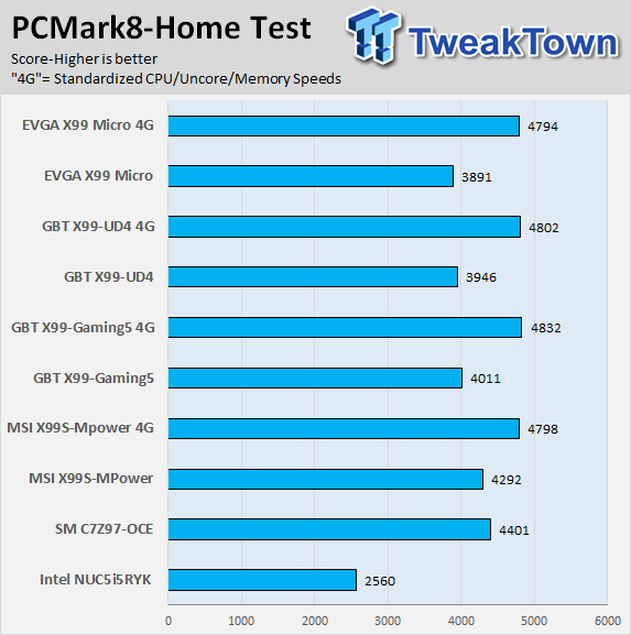
PCMark8 Home Test
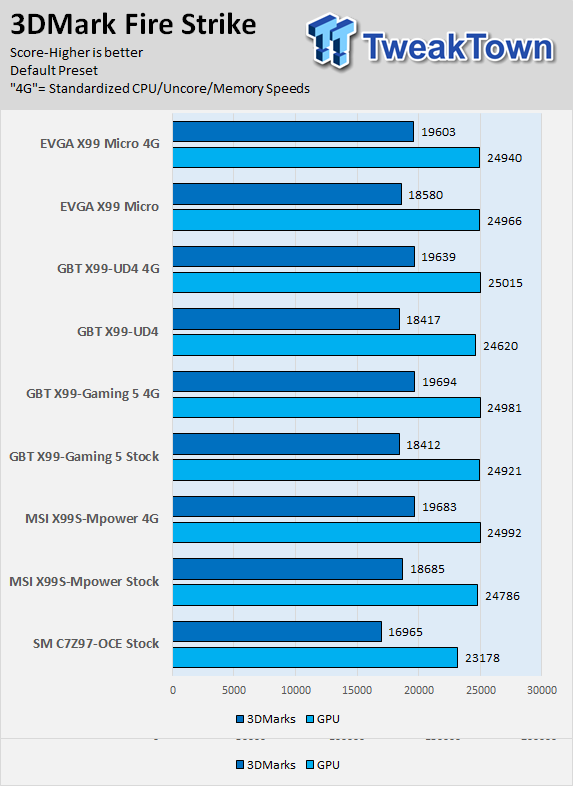
3DMark: Fire Strike
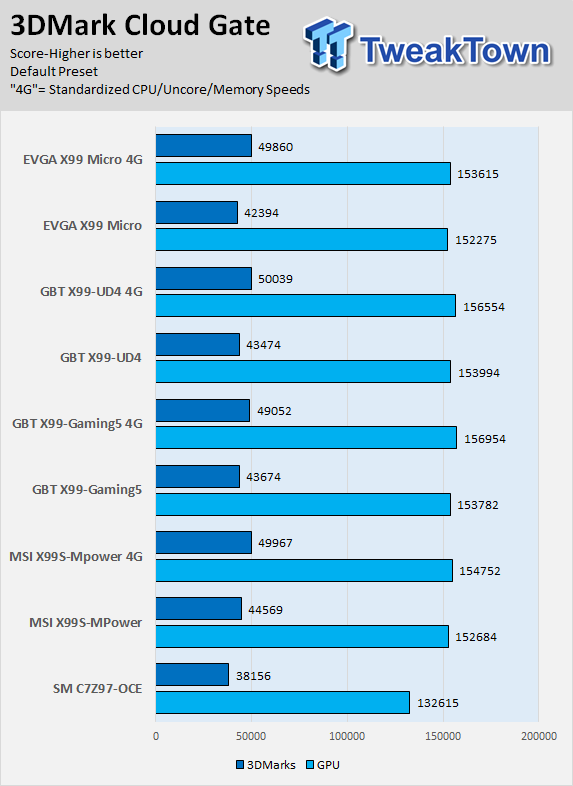
3DMark: Cloud Gate
Resident Evil 6
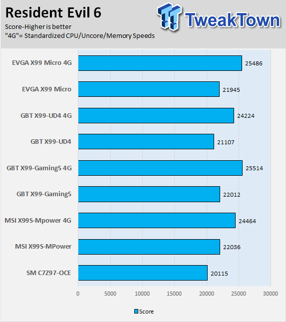
The X99-UD4 has strong CPU performance as you can see in CINEBENCH and the AIDA CPU tests I run, however, its memory performance is what keeps it back in benchmarks like HyperPI, possibly because its tertiaries are set a bit loose. When it comes to GPU performance, the X99-UD4 performs on an average level.
System IO Benchmarks
Anvil SATA6G:
Anvil M.2:
Diskbench USB 3.0:
ixChariot Network Throughput:
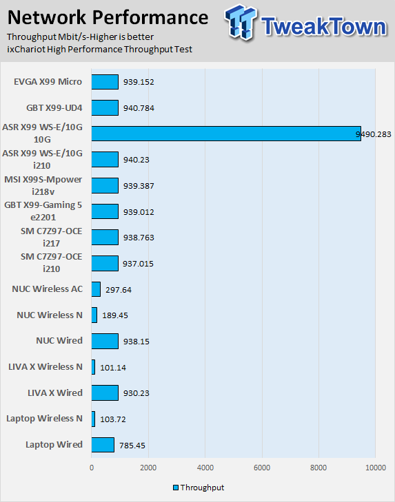
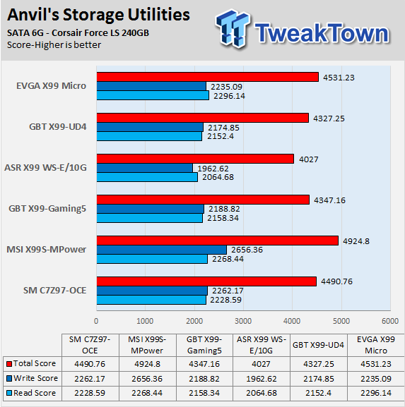
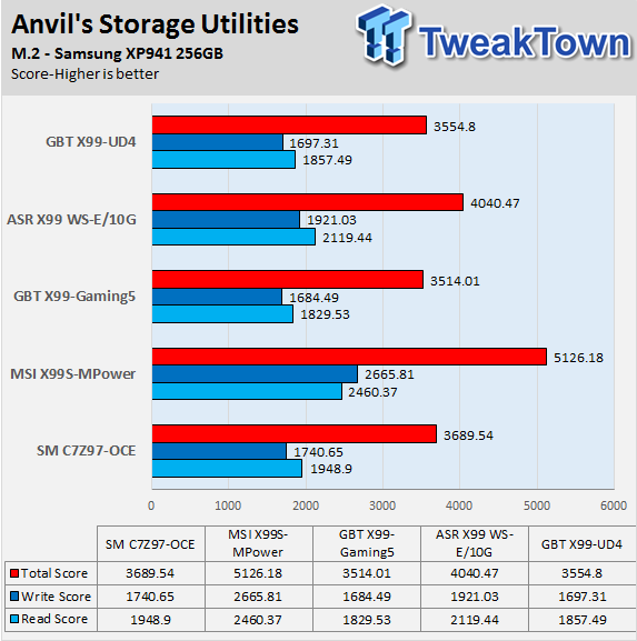
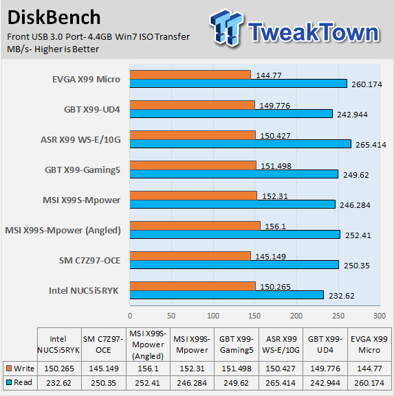
The M.2 performance isn't the fastest I have seen, but that makes sense since the M.2 slot on the X99-UD4 is 2x PCI-E 2.0. SATA and USB performance fall within acceptable ranges.
Network performance is what you would expect from an integrated Intel NIC and Intel PHY, the main advantage of the 218v is its power savings.
Audio RMAA 5.5:
I disable all audio features set the correct bitrates and then test the audio with a loopback test.
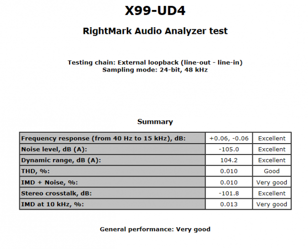
Sound Judgment by Ear: Very Good.
There are 5 ratings for audio: 1. Problems, 2. Okay, 3. Acceptable, 4. Very good, 5. Excellent
Temperature and Power Consumption
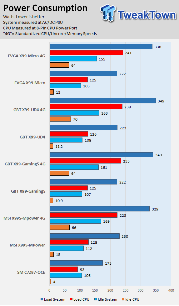
System power usage is measured at the AC/DC PSU (the Corsair AX1200i) which I have connected to another system to measure the test system and as a backup I have a wall meter to verify. The CPU power is measured through the 8-pin connect which is hooked up to a hall effect IC which measures current and puts out a voltage in proportion to the current. That voltage is logged by a National Instruments ADC which logs the DC voltage level, which I then convert into current.
Note on Thermal Images: In the temperature section, we use our Seek thermal imaging camera to capture the surface temperatures of major components on the board; I look at the VRM and then all other things that light up the screen. If there is something to worry about then I will state "you should worry about this:", otherwise I will just show the hotter running parts of the board for fun. Unless some component is over 80-90C then there really isn't anything to worry about. Also, orange is the brightest temperature imaged, it doesn't always mean orange is 80C or 30C. If everything is 0c on the screen and one thing is 5C, the thing that is 5C will be orange.
All systems will act differently, so I will look for commonalities, such as how far from the VRM the heat spreads through the PCB and the difference in temperature between the PCB and the chokes. Keep in mind that the majority of the heat from the VRM goes into the PCB as it is a giant soldered on copper heat sink.


Here the board is at stock and idle on the left and full CPU/Memory load on the right (Intel Burn Test).
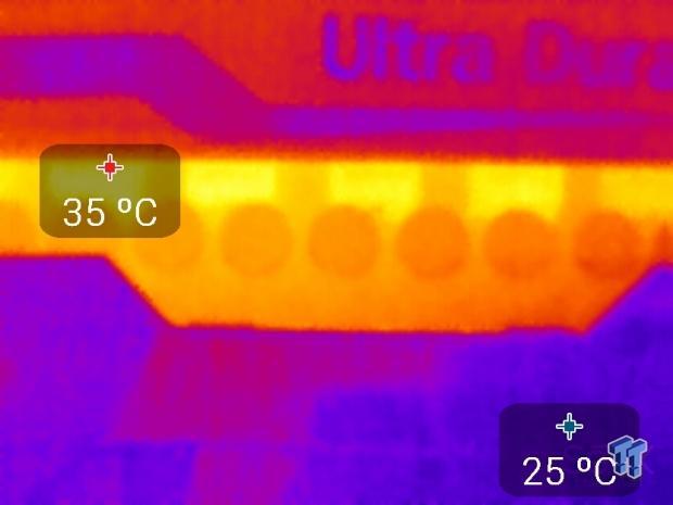
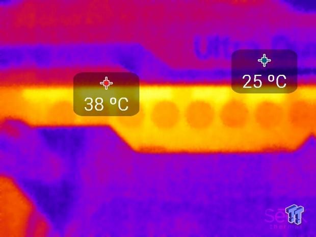
The VRM doesn't heat up too much during this strenuous load (at stock settings), which is a good sign. It seems the heat sink is taking care of much of the heat, the back is more telling.

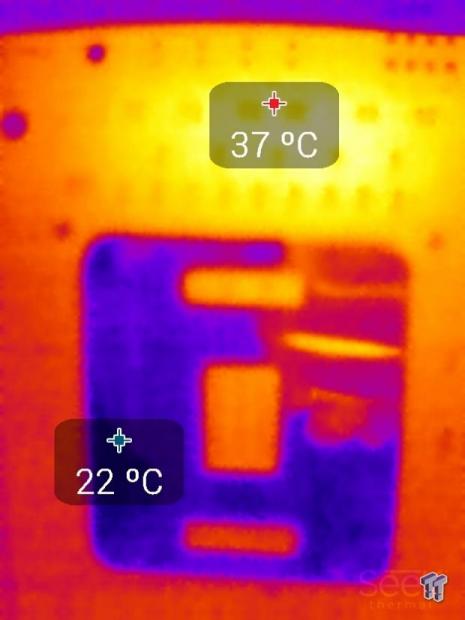
The back heats up a bit more than the front, still in safe ranges.


I cranked the system to 4.5GHz and ran the same tests. Here the whole system is at idle (no power saving states enabled) and then load. There is a considerable increase in temperatures.
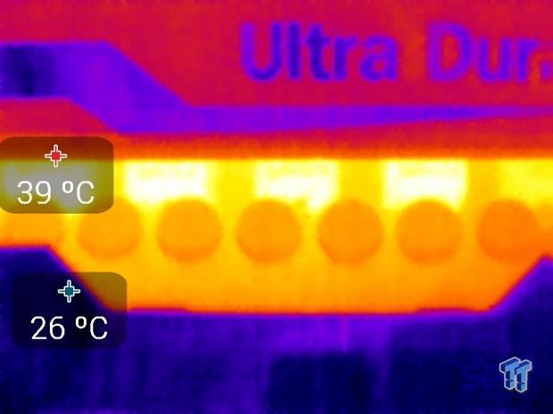
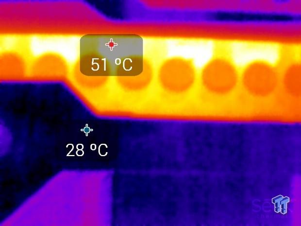
Here is the VRM from idle to load at 4.5GHz, there is a 12C increase.
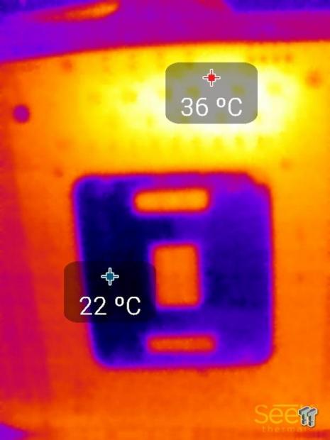
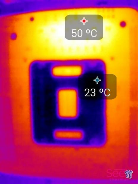
The back of the board shows a 14C increase. As long as the temperature at the back of the PCB is the same or lower than the temperature on the front side, the heat sink is doing its job and not saturated by heat. In this case, the heat sink is doing its job.
Temperatures are within totally acceptable ranges.
Final Thoughts
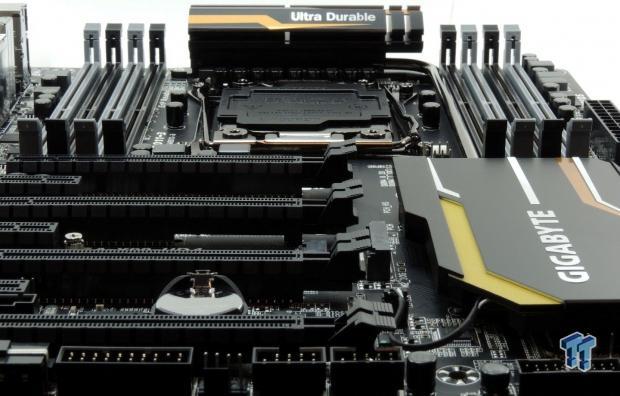
The X99-UD4 isn't a slouch, it performs up to par and its overall temperatures during overclocking were impressive. Power consumption was also very good and both my video cards got great airflow with the PCI-E layout. I didn't have any major issues other than the BIOS being a little picky when it comes to booting up with one of my USB thumb drives.
I also wish that the board had 4x of PCI-E bandwidth for the M.2 slot, but that's a tradeoff where a PCI-E slot or more SATA ports would be leveraged. Even without a POST code display, the board didn't prove problematic during overclocking. It booted every time, but I know how to dial in the settings.
A few weeks ago, I took the X99-Gaming 5 for a spin and the two boards seem to be built off the same premise. They have almost identical layouts and design, and while the Gaming 5 is aimed at gamers, the UD4 could do that job just fine as well. In overclocking tests, the two boards are similar, which isn't to say too much as most of the boards I have tested for the X99 chipset seems to perform the same. The big difference between the X99-UD4 and the X99-Gaming 5 is the audio section where the X99-Gaming 5 definitely has the advantage.
At the time of writing, the X99-UD4 is $255 right now on Newegg, and the X99-Gaming 5 is $270, which means for $15 more, you get an upgraded audio section with a replaceable amplifier, plus an amplifier for the front panel audio header. If you want flare, the X99-UD4 doesn't leave you hanging; the IO shield, PCB isolation, and PCH heat sink all light up, and while that might not matter to many of you, I know when I was younger I loved DFI boards for the same reasons.
Overall, I found that the X99-UD4 is a workhorse meant for users who want a solid X99 motherboard with strong performance and a robust feature set.
PRICING: You can find the GIGABYTE X99-UD4 (Intel X99) Motherboard for sale below. The prices listed are valid at the time of writing but can change at any time. Click the link to see the very latest pricing for the best deal.
United States: The GIGABYTE X99-UD4 (Intel X99) Motherboard retails for $249.99 at Amazon.
Canada: The GIGABYTE X99-UD4 (Intel X99) Motherboard retails for CDN$319.00 at Amazon Canada.

