Introduction
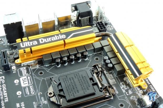
It's been a while since the Intel Z97 chipset was launched, and the GIGABYTE Z97X-UD5H was one of the first boards to hit the market. It features mostly everything one would expect from a Z97 board priced at $179.99; M.2, SATA Express, SLI/CrossFireX, and a nice set of hardware features to top it all off. While there are many Z97 boards, there isn't too much separating them, so I will dig into the motherboard's hardware and look at what GIGABYTE is offering up.
One could look at the aesthetic appeal of the motherboard as selection criteria for a new motherboard; in this case, the Z97X-UD5H features matte black PCB with a set of vibrant gold heat sinks, which have a strong shade of gold closer to the actual color of real gold. You wouldn't buy a car without popping the hood and checking out the engine, but since you can't get a close look at a motherboard before buying it, I will do it for you. I will also provide you with a complimentary overclocking guide for this motherboard.
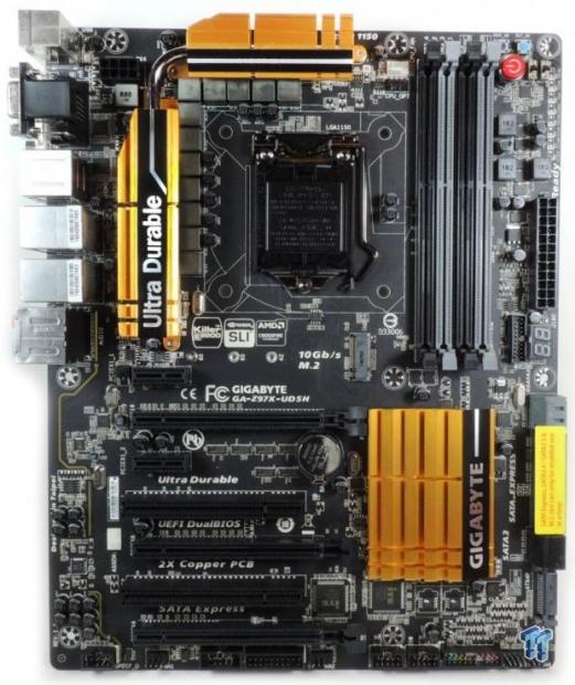
The Z97X-UD5H features a total of six fan headers; five of them have control in the UEFI and in Windows. The CPU fan header is the only one with both PWM(4-Pin) and Voltage(3-pin) control, which you can select. The rest of the fan headers are all voltage mode control, which can be used for both 4 and 3-pin fans.
Let's move onto the next page now and take a close look at the important voltage regulator circuitry.
PRICING: You can find the GIGABYTE Z97X-UD5H for sale below. The prices listed are valid at the time of writing but can change at any time. Click the link to see the very latest pricing for the best deal.
United States: The GIGABYTE Z97X-UD5H retails for $179.99 at Amazon.
Canada: The GIGABYTE Z97X-UD5H retails for CDN$222.02 at Amazon Canada.
Voltage Regulator Circuit Analysis
With more and more things being integrated into the CPU and PCH, there isn't much that sets motherboards apart, however, the voltage regulator is still one part of the motherboard that differs greatly between manufacturers, and even between models of the same brand. It is important to review the hardware to see exactly what you are paying for.
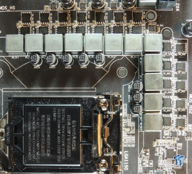
The CPU VRM features a total of 12 phases with Vishay PowerPAK Low RDS(ON) MOSFETs (Vishay calls them TrechFETs). These PowerPAKs are common MOSFETs used by a wide variety of manufacturers in lieu of traditional D-PAK MOSFETs. There are a total of 8 output capacitors, each at 560uF for a total of 4480uF slightly above the average we have seen on Z97 boards in this price range, these are custom made 10K capacitors from Nippon Chemi-Con. There are also 12x 0.5uH ferrite core inductors.
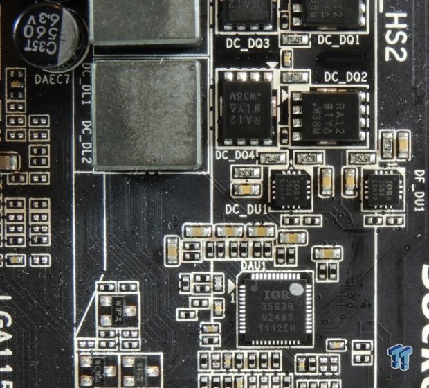
GIGABYTE has used the Vishay SiRA12 TrechFETs for both the high-side and low-side MOSFETs. They have used two MOSFETs per phase, which should be enough considering there are a total of 12 phases. GIGABYTE then employed an International Rectifier IR3563B digital PWM, a trusted 8-phase model used on many overclocking boards. However, only 6 out of the 8 phases are being utilized, those 6 phases are then doubled through the use of six International Rectifier IR3598s. The doublers are how GIGABYTE gets 12 phases, considering there are no 12 phase PWMs in use today.
The use of all International Rectifier control chips allows GIGABYTE to take full advantage of most of the PWM's features. There are no backside components on this VRM, and the board uses 2oz of copper in the power and ground layers, which provides cooling capacity through the PCB, and better signal quality. It might be relevant to mention that there seems to be no difference in the VRM between this board and the Black Edition of this board.
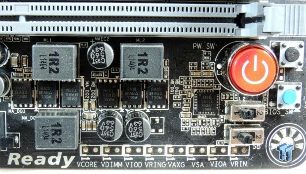
The memory VRM is made up of two phases using Vishay SiRA18 TrechFETs both for the low-side and high-side. The low-side features two MOSFETs per phase while a single MOSFET is used for the high-side, this makes for a total of three MOSFETs for each phase. An International Rectifier IR3570 digital PWM is used for the memory, it's a 3+2 phase PWM, and a single IR3598 is used as a dual driver (on the back of the board).
The IR3598 is an interesting chip because it has two operating modes. It can be used with a single PWM input and output two sets of driver signals, or it can be provided two PWM inputs and output two sets of driver signals. The first method would result in doubling, and the second is just space saving, and doesn't impact anything performance wise.
Motherboard Circuit Analysis
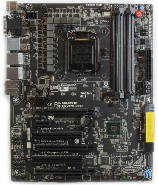
The Z97X-UD5H doesn't utilize any PCI-E lane expanders, meaning that the PCI-E lanes aren't shared by more than one device at the same time - this maintains high performance. GIGABYTE does this by routing the last PCI-E 4x slot to the CPU's PCI-E controller, instead of the PCH's PCI-E controller. This provides the ability to run the last 16x slot (actual 4x electrical) at PCI-E 3.0 speeds, which is aimed at multi-GPU configurations or faster PCI-E storage devices.
The fact that the PCH doesn't have four PCI-E lanes tied up by the 4x slot means that the Z97X-UD5H can offer dual NICs, extra SATA 6Gbps, two 1x slots, and two PCI slots, without impacting the performance of the controllers and attached devices. There is some sharing going on with a USB 3.0 hub, and I will cover that further down.
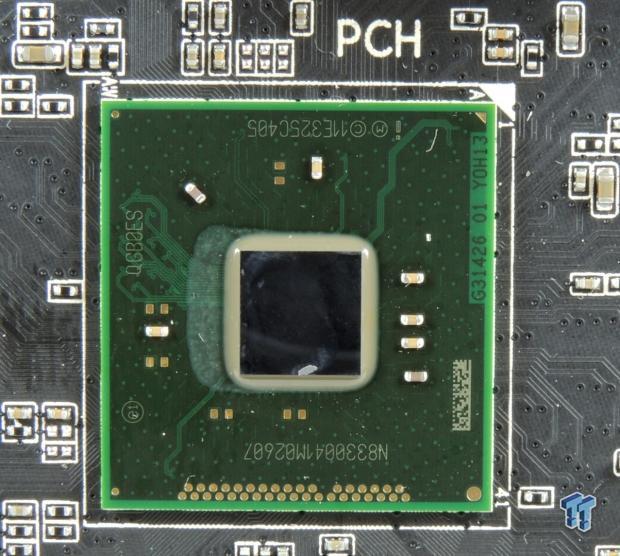
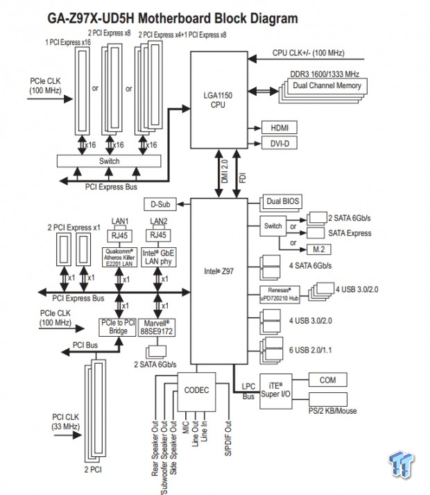
The PCH has a very low TDP of 4.1W, which means you really don't need a big heat sink to cool it down, I think most manufacturers make it big for aesthetic value. If you are interested, there is a block diagram from the manual showing all the connected devices. GIGABYTE is using the FlexibleIO configuration consisting of eight PCI-E ports, four SATA6GBps and six USB 3.0 ports. FlexibleIO allows SATA Express to operate off two PCI-E lanes that could have been used for SATA 6GBps.
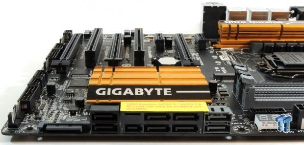
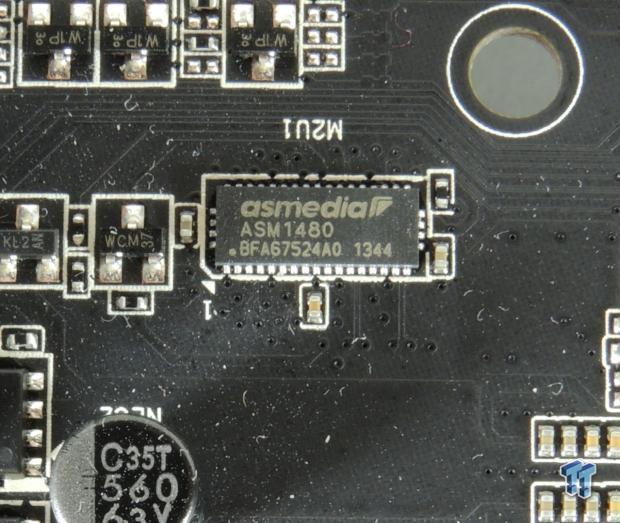
SATA Express is basically SATA over PCI-E bandwidth, the PCI-E bandwidth is enough to make it so that you can either use SATA Express or you can instead use the connectors for two SATA 6Gbps drives. The motherboard will detect what is in use and allocate accordingly. GIGABYTE has also added an M.2 slot; they do this by adding the ASM1480 pictured above, which is a 2 lane PCI-E 3.0 switch, so it can switch all the SATA Express bandwidth to the M.2 slot effectively disabling those ports.
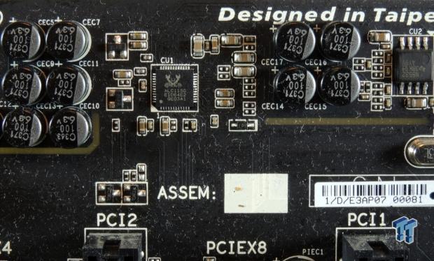
The audio section uses the ALC1150 rated at 115dB SNR in this case. GIGABYTE moved their amplifier to the back panel output as opposed to the front panel on the previous generation of boards, and they have given the amplifier an upgrade. The amplifier is a Texas Instruments NE5532 and supports 600ohm output impedance.
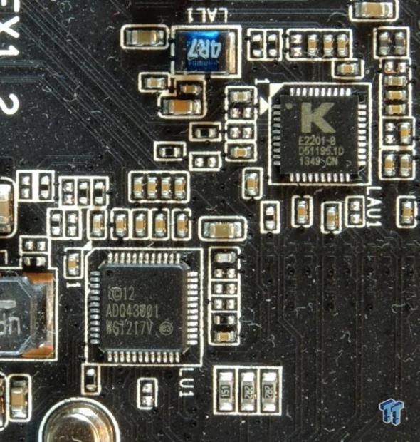
The Z97X-UD5H features dual NICs, giving the user the choice between an Intel i217v and a Qualcomm Killer e2201.
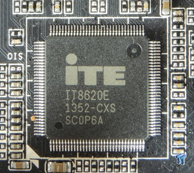
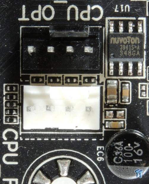
GIGABYTE is using an iTE8620E for its SuperIO which does all the hardware monitoring and provides some fan control. It is also responsible for the PS/2 port on the back. To supplement the fan control of the iTE8620E and provide fan control for the fan headers, GIGABYTE chose to employee four Nuvoton 3941S chips, these provide fan control for each header (CPU fan header goes off the iTE8620E).
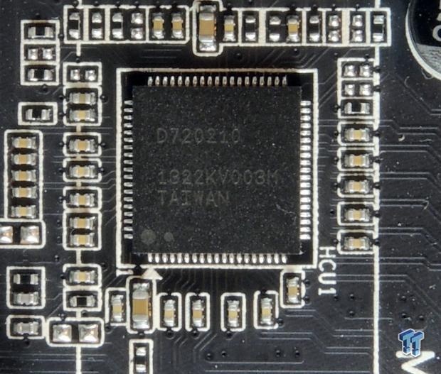
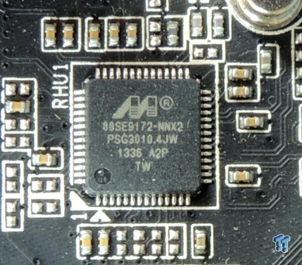
The Renesas D720210 is a 1:4 USB 3.0 hub. It takes in 1 USB 3.0 port and outputs 4. The four topmost USB 3.0 ports on the back panel go through this hub. The internal header and the USB 3.0 under the bottom NIC go directly to the CPU. Extra SATA 6Gbps is provided by a Marvell SE9172, those are the gray internal SATA ports.
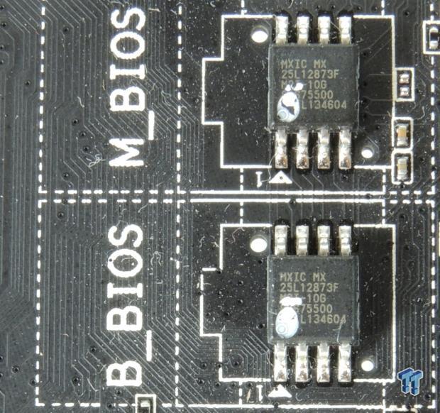
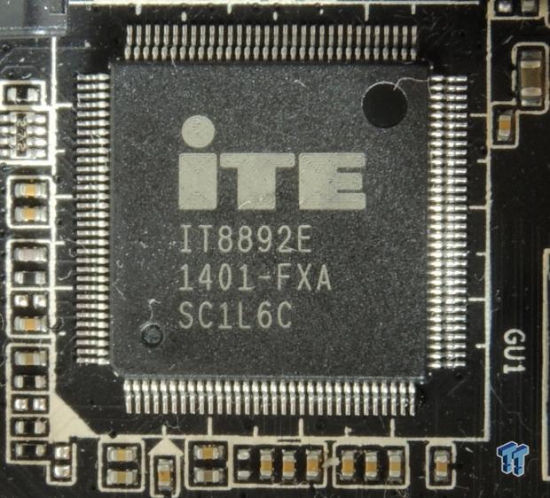
There are two BIOS ROMs, these are each 128Mbit/16MB. They only other manufacturer I have seen use 16MB BIOS ROMs is Supermicro. The BIOS on these GIGABYTE boards is basically double the size as most other boards on the market. The iTE8892E takes one PCI-E port and turns it into two PCI ports you see on the board.
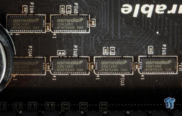
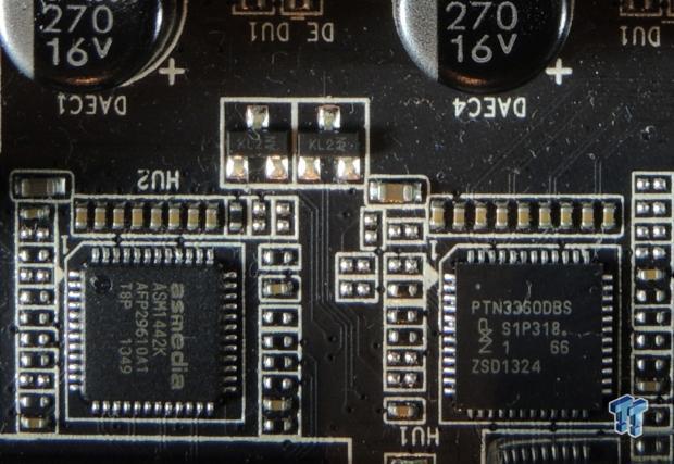
Six ASM1480 are quick switches, they are two lane PCI-E 3.0 switches and they are used to allocate PCI-E lanes allowing 2-way SLI and CrossFireX at 8x/8x and 3-way CrossFireX at 8x/4x/4x. The ASMedia and NXP chips are both level shifters, one is optimized for DVI and the other HDMI, as the digital video output of the IGP needs to be altered to be displayed on those two busses.
Overclocking and BIOS Setup
Overclocking Results
In this section, I will go through overclocking this board. Overclocking (OC) is a strong indicator of overall tuning. I don't only OC the CPU, but also the memory, and even the base clock with the latter having more to do with board design and BIOS tuning.
CPU and BCLK Overclocking
Max CPU Overclock is found by setting the VCore to 1.4v, Input voltage to 2.0v, cache voltage to 1.2v, CPU multiplier to 45x, memory and cache multipliers to 8x, and disabling any features that would result in CPU frequency fluctuation (disabling C states and EIST in the GIGABYTE UEFI). I then proceed into Windows and use software to increase the multiplier; in this case I opted to use GIGABYTE Tweak Launcher (GTL), which is a slim program only meant for changing overclocking parameters in Windows.
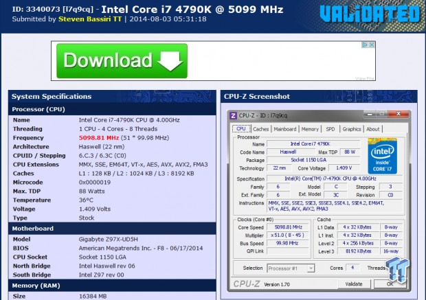
5.1GHz is the maximum of our CPU on many boards; the Z97X-UD5H did as expected. Maximum AIDA64 Stable Overclock (BIOS settings are located further down):
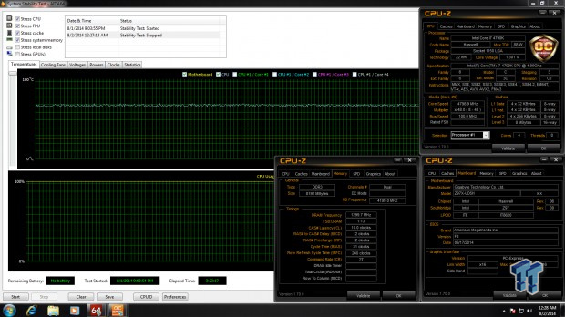
I was easily able to pull off 4.8GHz on the CPU with 4.2GHz cache and a 2600MHz XMP overclock on my memory by manually tuning the UEFI. Later on I will cover GIGABYTE's auto OC features and their overclocks.
Max BCLK is found at the 1.67x (if it's operational), with fixed PCH Core voltage of 1.25v and fixed PCHIO at the lowest the board will allow, I believe 1.05v here. All other ratios are tuned back to 8x to ensure they don't bottleneck the BCLK overclock.
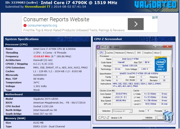
189.86MHz was the maximum BCLK OC I could pull off with optimal settings.
Memory overclocking with Hynix (double sided 8GB modules)
Maximum clock on this memory was done by using the 1.00x divider for BCLK, and then using timings of 12-15-15-35 2T, with 1.700v for DRAM voltage, and +0.20v for VCCIOA, VCCIOD, and System agent. The CPU and cache ratios were reduced to 8x to make sure they didn't affect the overclock. An efficiency test is also run, since every manufacturer sets their sub-timings differently, this test can also be used for comparison, same timings are set (no XMP of course), and a divider of 28x was used.
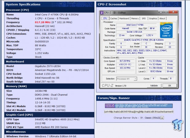
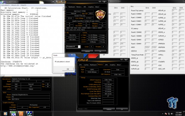
- Max Hynix(double sided) OC: 2996 MHz
- Hynix efficiency time: 44.351s
Memory overclocking with Samsung (double sided 4GB modules)
Maximum clock on this memory was done by using the 1.00x divider for BCLK, and then using timings of 9-12-12-25 1T, with 1.900v for DRAM voltage (Samsung likes voltage, and this is strictly for motherboard testing purposes), and +0.15v for VCCIOA, VCCIOD, and System agent. The CPU and cache ratios were reduced to 8x to make sure they didn't affect the overclock. An efficiency test is also run, since every manufacturer sets their sub-timings differently, this test can also be used for comparison, same timings are set (no XMP of course), and a divider of 26.66x was used.
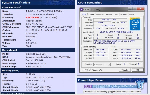
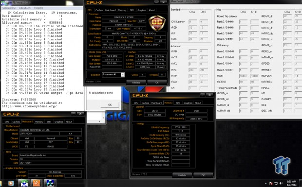
- Max Samsung OC: 2731
- Samsung efficiency time: 44.631s
BIOS Settings for 4.8GHz Overclock with XMP
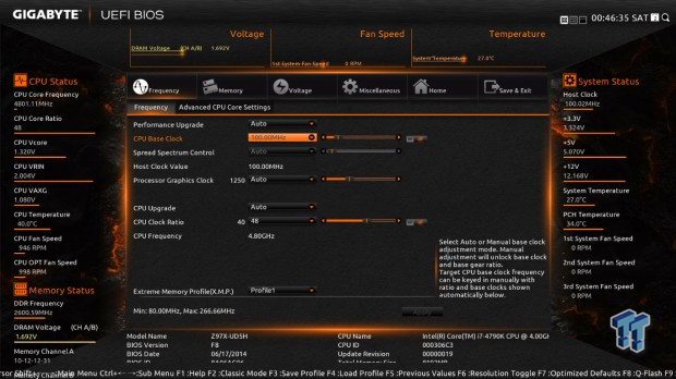
I just typed in the CPU multiplier here, enabled XMP (I didn't need to visit the memory page), and set the BCLK to 100.00, you can also set it to 100.02 to get 100.00 MHz even.
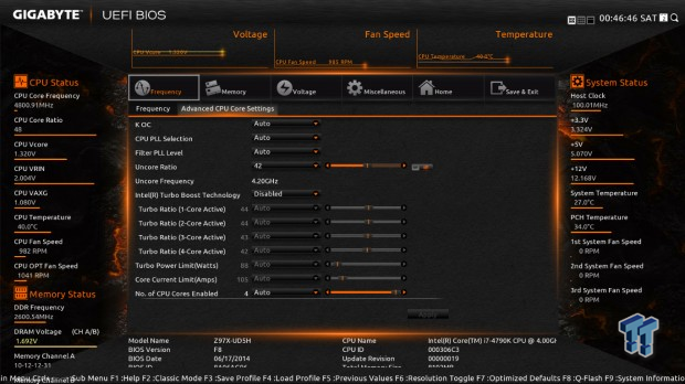
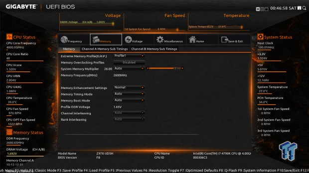
I disabled Turbo mode, but you can leave it on Auto, and then I disabled all the c-states and EIST. I also set the uncore ratio to 42x here as well. The memory tab doesn't need to be visited if all you set is XMP, however, there are many more options to tune if you desire. The one I find most useful for extreme overclocking on boards like the Z97X-SOC Force is the fast boot enable/disable option, so you can control memory training to some extent.
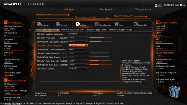
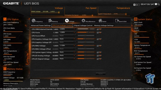
The advanced power menu is where you see all the options for the IR3563B digital PWM; I set VRIN LLC to "Extreme" and PWM Phase control to "eXm Perf" on all GIGABYTE boards I overclock, however, on the Z97X-UD5H, it is also a good idea to set the VRIN Current Protection to "Extreme" to make sure the CPU sustains a high current overclock such as that at 4.8GHz. I set the voltages as in the second picture above; there isn't a need to set the DRAM voltage as XMP takes care of that.
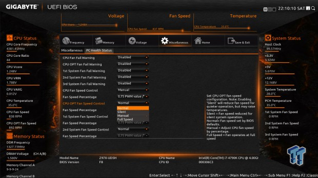

If you want to change your fan control settings, they are readily available here; the speed percentage however could be a bit tricky, basically 2.5x is more reactive to higher temperatures than 0.75x.
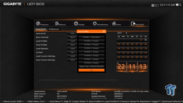
If you would like to save your BIOS profiles for later, you may do so in this menu.
OC Recovery Experience
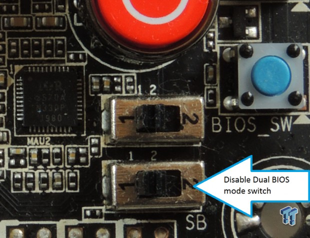
I would say that the overclocking recovery on this board is pretty good for CPU and memory.
BCLK OC recovery took longer to occur than CPU or memory, possibly because of the dual BIOS function; however, that can be disabled by an onboard switch.
Test System Setup and Feature Testing
Test System Setup
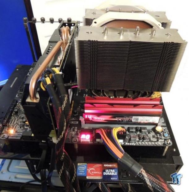
In this section, I will test GIGABYTE's features; EasyTune "Auto Tuner", BIOS CPU OC Profiles, power consumption, and audio performance.
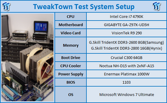
GIGABYTE's EasyTune "Auto Tuner" and BIOS OC Profiles
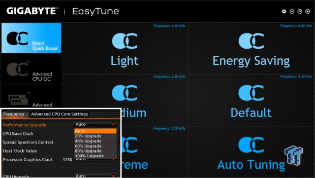

GIGABYTE has two ways to auto overclock your CPU, one of those ways is the Auto Tuner, which will increase the CPU frequency and voltage and test for stability over and over until it stops where it's unstable, then it will reduce back to where it was stable. The other way is the Smart Quick Boost/Performance Upgrade in the UEFI; this method has preset profiles for overclocking.
The issue with motherboard auto overclocking in general is the fact that programs like auto tuning do their thing quickly and the profiles have to work for all overclocks. In general, auto overclocking provides much more voltage to the CPU than you would need if you manually did the overclock.
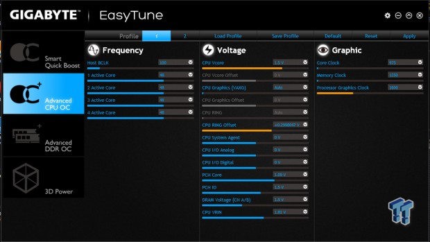
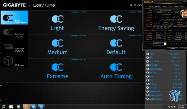
With one press of that large button, the system goes into a cycle of testing settings and reboots, and finally comes out with a result. Auto Tuning resulted in both the highest auto overclock we have seen and the highest voltage we have seen. A CPU frequency of 4.8GHz is right where my manual overclocking led me; however, a VCore of 1.5v is way above the amount needed for my overclock.
GIGABYTE does this to ensure that all processors will work at specified speeds. My suggestion would be if you use this program, then you should set your voltages yourself, perhaps start a bit lower than what it sets and go from there.
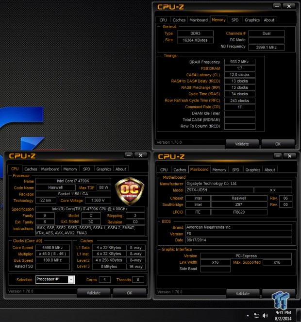
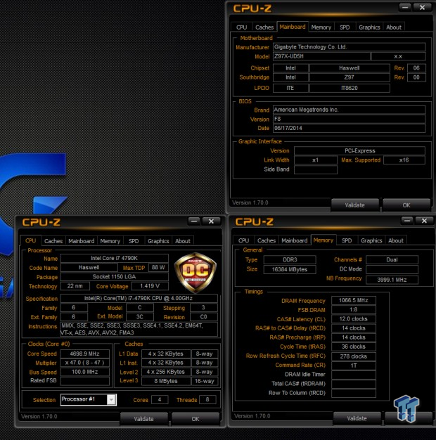
The performance upgrade profiles in the UEFI yield more reasonable overclocks. I tested the top two settings; 80% and 100%. The 80% resulted in a 4.6GHz overclock on the CPU and 1.36v VCore, it also overclocked the memory to 1866MHz. The 100% overclock resulted in a 4.7GHz overclock on the CPU and 1.42v VCore, it overclocked the memory to 2133MHz. The voltages seem a bit more reasonable for the speeds, while still high, they should ensure your CPU will run at those speeds.
Power Testing
I tested the power at the wall socket and at the 8-Pin CPU power connector on the motherboard, which supplies the CPU power. Measurements were taken at 0% load for Idle and 100% load (at max spikes) using IntelBurnTest.
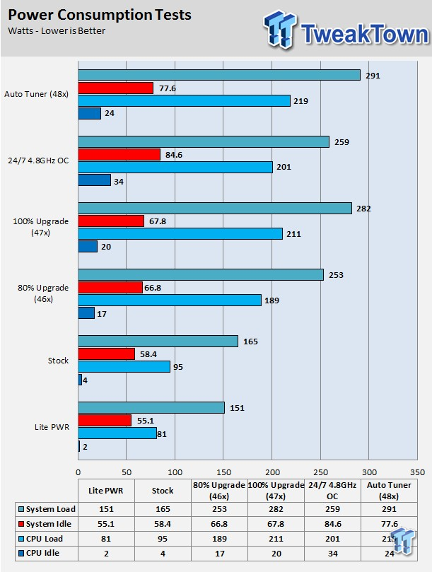
Windows power settings:
- Power Saver: Lite PWR
- Balanced: Stock, 80% Upgrade, 100% Upgrade
- High Performance: 4.8GHz Manual OC, Auto Tuning
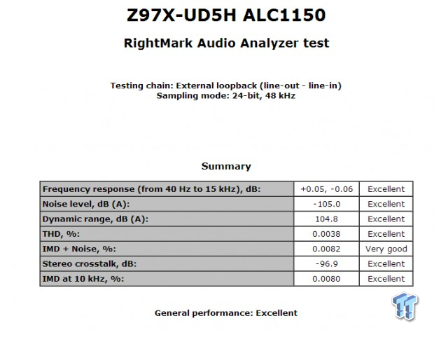
This is the testing done in RMAA5.5 with the audio, the results speak for themselves. I test with RMAA a bit differently than others; I make sure to disable all audio enhancements in packaged software and in the control panel, then I match bit rate and frequency, and finally run the test.
Final Thoughts
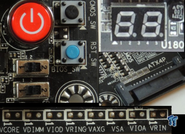
GIGABYTE's Z97X-UD5H motherboard is a strong contender when it comes to features and overclocking, its hardware tells that story well. However, we didn't really cover its overclocking features, as you can see above there are plenty. One thing that I really admire is when a Z97 board has voltage read points, considering most of the voltage rails are integrated into the CPU, the only way to read them with a digital multi-meter is if the manufacturer provides read points, which GIGABYTE does here.
GIGABYTE has added four extra Nuvoton fan controller chips to provide users with control over more than just the CPU fan header, but I would have liked to see more PWM capable headers, however, all headers support 3 pin (voltage) and 4 pin (PWM) fans. Auto Tuning overclocking could also be improved to better optimize voltages. I would recommend manually typing in voltages into the UEFI if you decide to go this route for auto CPU overclocks over 4.5GHz.

The voltage regulator has top notch control hardware and features a versatile array of controller chips, which can provide high overclocks, as well as extremely low power usage, depending on what the user demands. Overclocking went well, CPU and BCLK overclocking matched boards we have previously tested. This board handles Samsung based DDR3 modules very well, providing both higher speeds and slightly better efficiency, compared to other boards we have tested. While Hynix based memory efficiency is good, its top speeds were slightly lower than some other boards we have tested.
Manufacturers usually tune their UEFIs and set their auto rules (timings) to favor efficiency or frequency, in this case, I would say the UEFI is tuned for efficiency, while the hardware seems to favor certain modules. GIGABYTE is known for making quality motherboards with innovative designs tuned towards signal integrity; this is evident in our overclocking tests as this board can hold its own compared to higher-end overclocking boards.
The Z97X-UD5H is a solid contender for anyone looking for a 24/7 motherboard which will also handle a high speed overclock.
PRICING: You can find the GIGABYTE Z97X-UD5H for sale below. The prices listed are valid at the time of writing but can change at any time. Click the link to see the very latest pricing for the best deal.
United States: The GIGABYTE Z97X-UD5H retails for $179.99 at Amazon.
Canada: The GIGABYTE Z97X-UD5H retails for CDN$222.02 at Amazon Canada.

 United
States: Find other tech and computer products like this
over at
  United
Kingdom: Find other tech and computer products like this
over at
  Australia:
Find other tech and computer products like this over at
  Canada:
Find other tech and computer products like this over at
  Deutschland:
Finde andere Technik- und Computerprodukte wie dieses auf